
Multimeric dye structures

a dye structure and multi-meric technology, applied in the field of dye-based inkjet imaging, can solve the problems of difficulty in satisfying all of the above characteristics, and achieve the effect of good water fastness

Inactive Publication Date: 2007-01-02
HEWLETT PACKARD DEV CO LP
View PDF17 Cites 4 Cited by
  • Summary
  • Abstract
  • Description
  • Claims
  • Application Information

AI Technical Summary

Benefits of technology

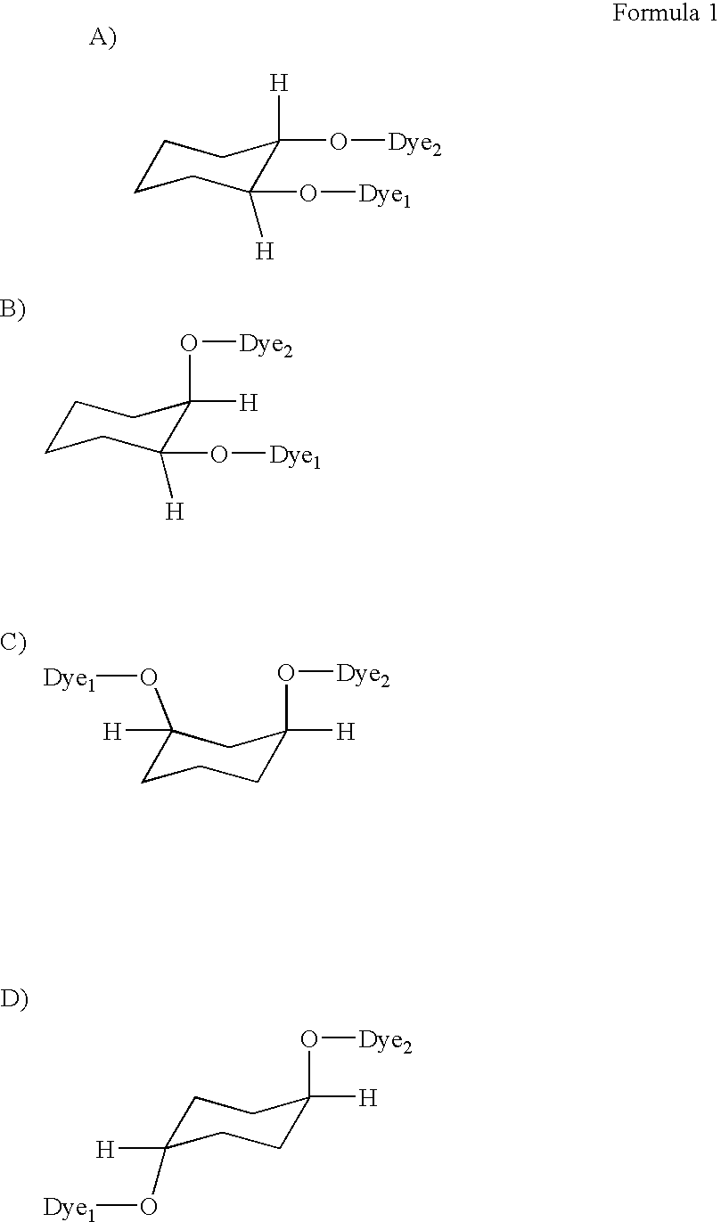
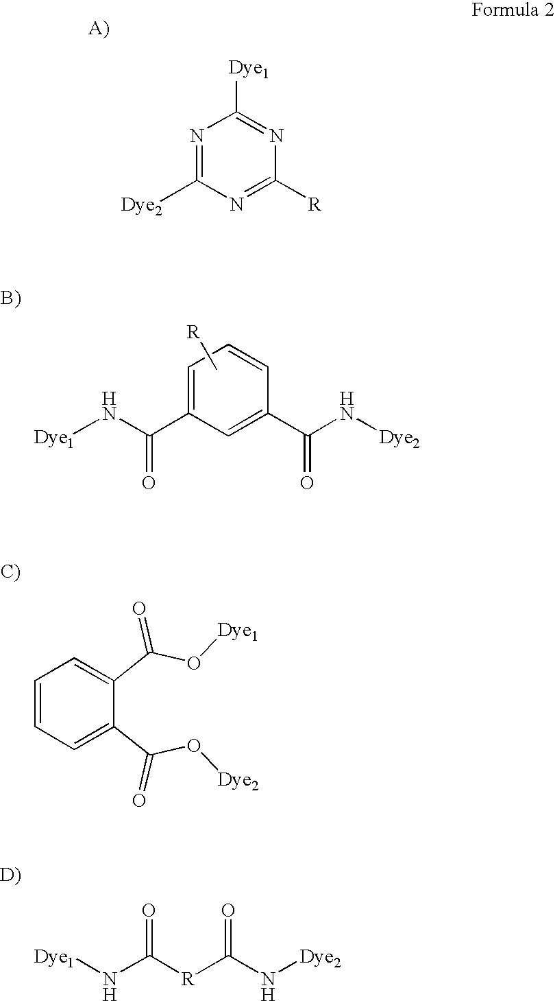
[0008]It has been recognized that certain multimeric dye structures can provide good water fastness and humid fastness, and can perform well on specialty media, such as porous media. In accordance with this recognition, a multimeric dye for ink-jet printing in accordance with embodiments of the present invention can comprise a first dye molecule chemically coupled to a second dye molecule through a linker group, wherein the multimeric dye as a whole is substantially stable in the presence of interfering metals.

Problems solved by technology

Though the above lists of characteristics provide a worthy goal, there are difficulties associated with satisfying all of the above characteristics.
Though dye-based ink-jet inks can provide good color characteristics, water fastness and humid fastness of printed images, particularly on porous media, can remain a challenge, as exposure to water or humidity after printing can cause color shift and / or dye migration, for example.

Method used


Image

  • Multimeric dye structures
  • Multimeric dye structures
  • Multimeric dye structures

Examples


example 1

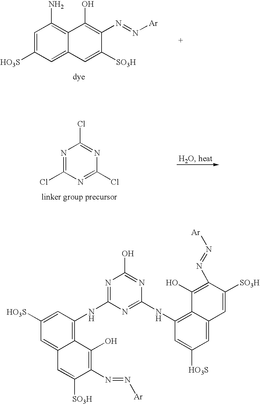
[0046]Two NH-dyes are coupled to a triazine linker group precursor according to the following reaction scheme.

[0047]

[0048]In the above reaction scheme, Ar can be an aryl or substituted aryl group. The dye can be reacted with the linker group precursor at a 2:1 molar ratio. Two chlorines of the linker group are replaced by two dye molecules at their respective NH2 groups, and the HCl is formed as a byproduct. The third chlorine of the linker group can then be reacted with excess water in the presence of heat, e.g., about 80° C., causing replacement of the third chlorine with a hydroxyl group, wherein additional HCl is formed. This reaction can be conducted in the presence of a polar organic solvent that does not, of itself, attack the chlorine on the linker group. An exemplary solvent that can be used includes tetrahydrofuran.

example 2

[0049]Two NH-dyes are coupled to a diacid linker group precursor according to the following reaction scheme.

[0050]

[0051]In the above reaction scheme, Ar can be an aryl or substituted aryl group. The dye can be reacted with a cyanuric chloride linker group precursor at a 2:1 molar ratio according to one of a several reaction schemes. In a first embodiment, the dye can be reacted with triphenylphosphine triflate [Ph3P(OTf)2], and then reacted with the linker group precursor. In a second embodiment, triphenylphosphine and tetrachloromethane can be reacted with the dye to prepare the dye for reaction with the linker group precursor. In a third embodiment, dicyclohexylcarbodimide and ethyl ether can be used to prepare the dye for reaction with the linker group. In a fourth embodiment, the acid groups of the linker group can be converted to an ester, such as by tosylating the linker group precursor and reacting it with the dye. Other means of linking the dyes to linker group precursors ca...


PUM

PropertyMeasurementUnit
sizeaaaaaaaaaa
wt %aaaaaaaaaa
sizeaaaaaaaaaa

Abstract

The present invention is drawn to multimeric dyes, ink-jet inks, and systems that can be used to print images having good water fastness and humid fastness, as well as good color characteristics. Specifically, a multimeric dye for ink-jet printing can comprise a first dye molecule chemically coupled to a second dye molecule through a linker group, wherein the multimeric dye is stable in the presence of interfering metals. These multimeric dyes can be used to form ink-jet inks and can be used in printing systems in accordance with embodiments of the present invention.

Description

FIELD OF THE INVENTION[0001]The present invention is drawn to dye-based ink-jet imaging. More specifically, the present invention is drawn to substantially stable multimeric dye structures coupled together by a linker group.BACKGROUND OF THE INVENTION[0002]As the ink-jet printing field develops, improvements in printing characteristics such as edge acuity, optical density, substrate adherence, dry time, resolution, durability, and waterfastness continue to be explored. At the same time, while trying to improve upon these characteristics, fluids of the ink-jet system should also provide long term storage compositional stability and long term reliability without equipment corrosion or nozzle clogging. Though the above lists of characteristics provide a worthy goal, there are difficulties associated with satisfying all of the above characteristics. Often, the inclusion of an ink component meant to satisfy one of the above characteristics can prevent another characteristic from being me...

Claims


Application Information

Patent Timeline
Patent Type & Authority Patents(United States)
IPC IPC(8): C09D11/00C09B69/00
CPCC09D11/328C09D11/32
Inventor DEARDURFF, LARRIE A
Owner HEWLETT PACKARD DEV CO LP
Learn More