Infrared sensor package

Inactive Publication Date: 2007-01-02
MATSUSHITA ELECTRIC WORKS LTD
View PDF8 Cites 3 Cited by
  • Summary
  • Abstract
  • Description
  • Claims
  • Application Information

AI Technical Summary

Benefits of technology

[0003]In view of the above problem the present invention has been achieved to provide an improved infrared sensor package which is capable of being manufactured at a reduced cost, yet retaining compactness. The infrared sensor package of the present invention includes a dielectric support which is molded from a plastic material to have a sensor mount for securing a pyroelectric element as well as an IC mount for securing an IC chip that processes a signal from the pyroelectric element. The support is held on a base which is formed with a plurality of I/O pins extending through the base for electrical connection of the IC chip with an external circuit. A cover is secured to the base to give a space therebetween for accommodating t

Problems solved by technology

However, the conductor pattern can be only realized through several processes with the

Method used


Image

  • Infrared sensor package
  • Infrared sensor package
  • Infrared sensor package

Examples


Embodiment Construction

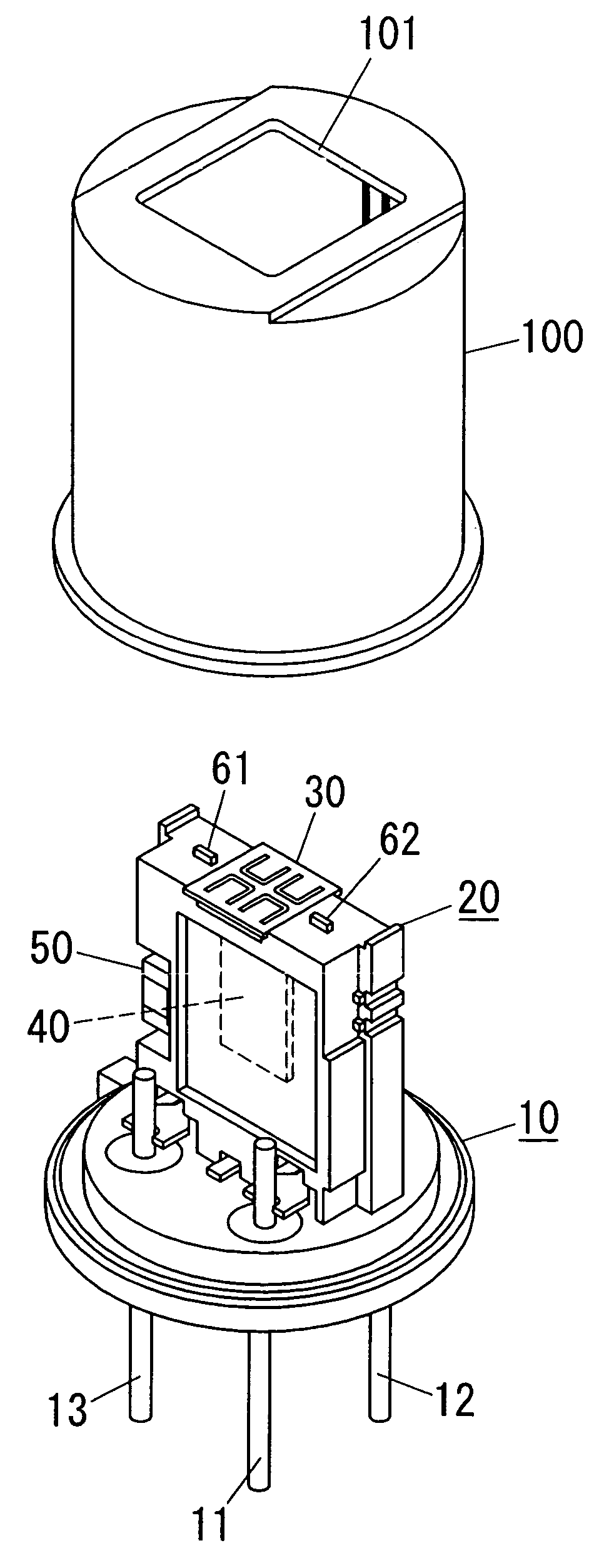
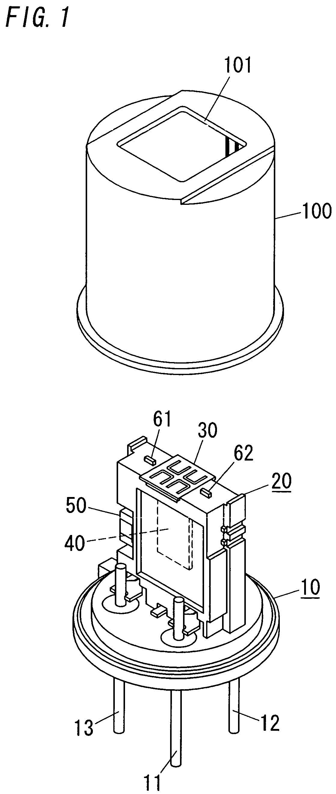
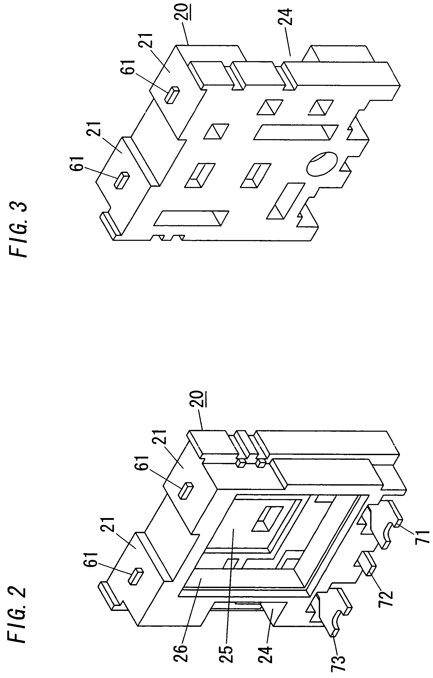
[0038]Referring now to FIG. 1, there is shown an infrared sensor package in accordance with a preferred embodiment of the present invention. The infrared sensor package is provided, for example, to detect human presence in the room or area in order to give a warning or control an associated lighting device or the like. The package is basically composed of a base 10 carrying a dielectric support 20, I / O terminal pins 11 to 13, and a cover 100 fitted over the support 20 on the base 10. The dielectric support 20 retains a pyroelectric element 30, an IC chip 40 forming a signal processing circuit, and an electronic component 50 to be connected to the circuit of the IC chip 40. The pyroelectric element 30 generates a signal output upon receiving infrared radiation through a transparent window 101 in the top of the cover 100. As shown in FIG. 10, the signal processing circuit realizes a current-voltage converter 41 for converting the signal output in the form of a current into a voltage, ...


PUM


Abstract

An infrared sensor package has a dielectric support which is molded from a plastic material to have a sensor mount for securing a pyroelectric element as well as an IC mount for securing an IC chip that processes a signal from the pyroelectric element. The support is molded over to be integral with metal parts. The metal parts include sensor conductors for interconnection of the pyroelectric element with the IC chip, and I/O conductors for interconnection of the IC chip with I/O pins. The sensor conductors as well as the I/O conductors are both molded into and integrally with the dielectric support.

Description

TECHNICAL FIELD[0001]The present invention is directed to an infrared sensor package, and more particularly to an infrared sensor package of a self-contained type incorporating a pyroelectric element as well as an IC chip which processes a signal output from the element for providing a determined sensor output.BACKGROUND ART[0002]U.S. Pat. No. 6,121,614 discloses an infrared sensor of the above self-contained type having a dielectric support on which the pyroelectric element as well as the IC chips are mounted. The support is held within a space between a base and a cover. The base has I / O pins that are connected to the IC chip and projects for connection with an external circuit. In order to electrically connect the IC chip to the pyroelectric element, external electric parts, and the I / O pins, the support of generally cuboid configuration is formed with a complex conductor pattern extending across two or more outer surfaces of the support. However, the conductor pattern can be onl...

Claims


Application Information

Patent Timeline
IPC IPC(8): G01J5/34G01J5/04
CPCG01J5/02G01J5/0205G01J5/34G01J5/045G01J5/04
Inventor TANIGUCHI, RYOTAKADA, YUJIKODOH, MASAHIROSHINOTANI, MASATOTANAKA, HISANOBUHIRONAKA, ATSUSHI
Owner MATSUSHITA ELECTRIC WORKS LTD
Why Eureka
Try Eureka