Image display medium ribs, production process thereof, and image display medium using the ribs

Active Publication Date: 2007-01-02
E INK CORPORATION
View PDF9 Cites 16 Cited by
  • Summary
  • Abstract
  • Description
  • Claims
  • Application Information

AI Technical Summary

Benefits of technology

[0027]According to the image display medium ribs and production process thereof of the present invention, an effect is achieved in that it is possible to provide a high-image quality image display medium with a cell-form arrangement, a narrow rib w

Problems solved by technology

Therefore, there is a problem in that an open area ratio of the image display medium is reduced.
However, with photolithography utilizing a dry film, because of exudation of an etching solvent, defects will occur frequently if the ribs are made thinner.
Further, with a sandblasting process utilizing a resist material, if the ribs are made thinner, lateral impacts from blasting particles

Method used


Image

  • Image display medium ribs, production process thereof, and image display medium using the ribs
  • Image display medium ribs, production process thereof, and image display medium using the ribs
  • Image display medium ribs, production process thereof, and image display medium using the ribs

Examples


example 1

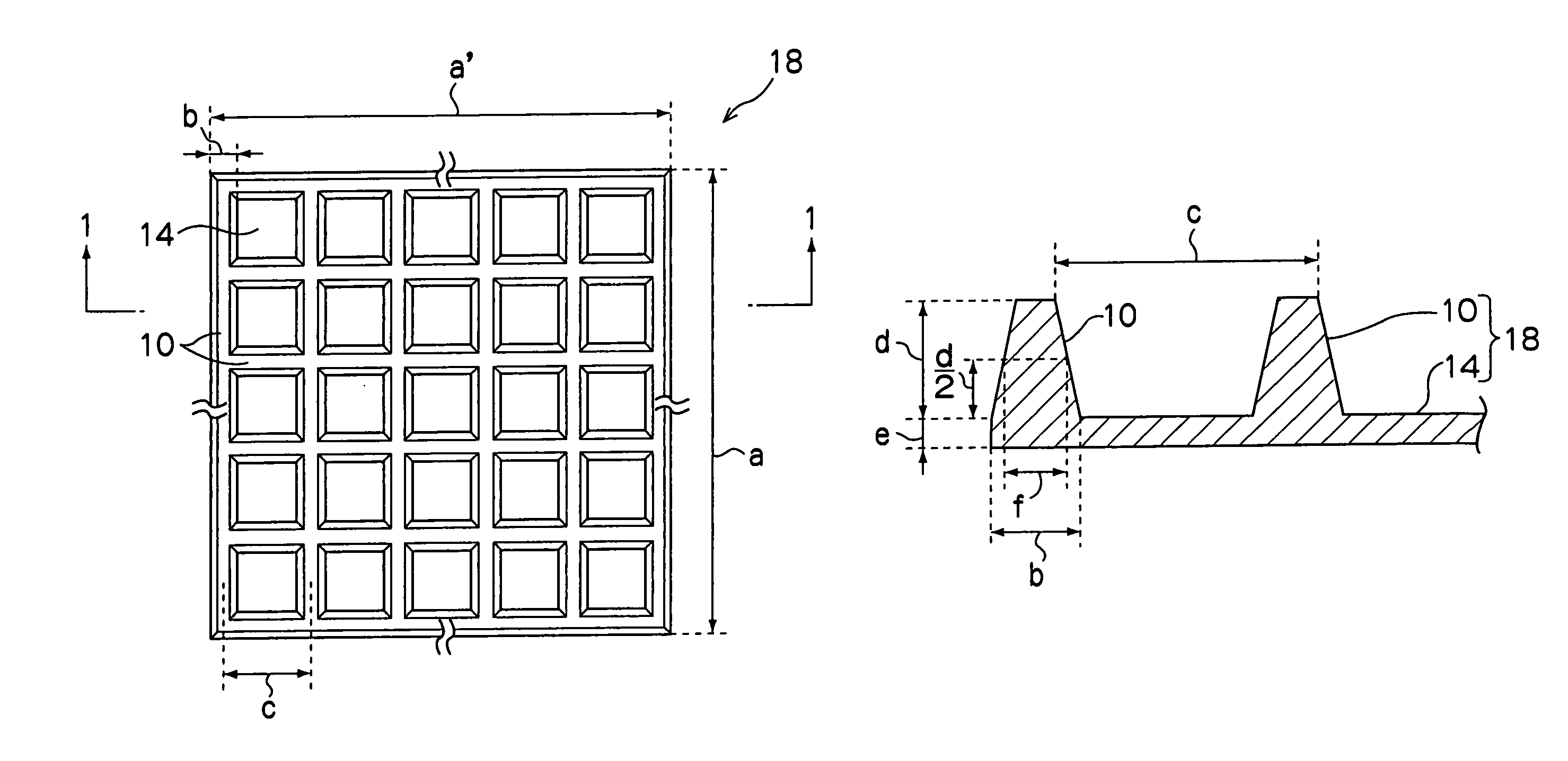
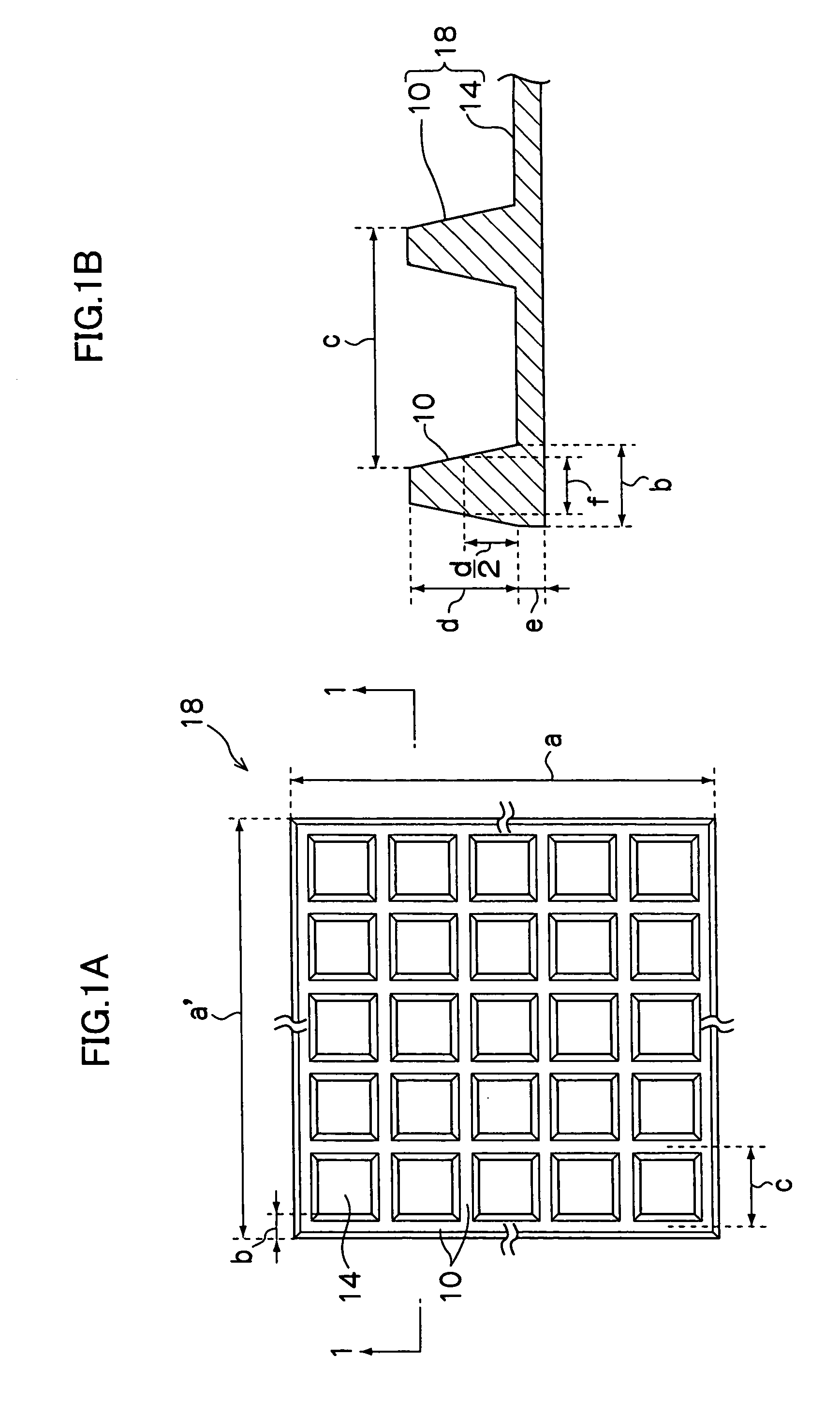
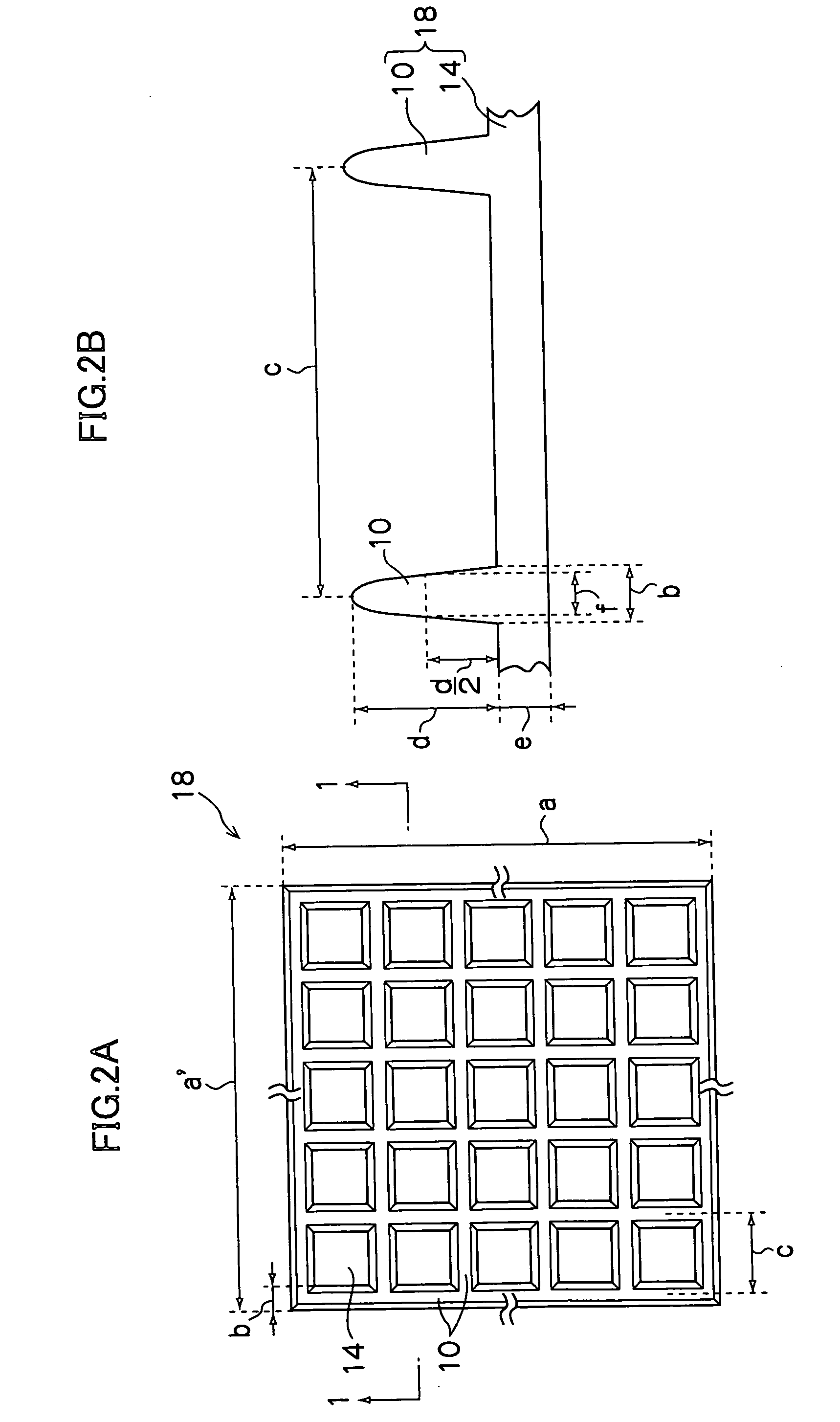
[0093]A mold is prepared which is machined to a rib height of 200 μm, a rib base width of 100 μm, a rib half-height width of 60 μm with rib side walls sloping in straight lines (i.e., the rib side walls have tapered forms), a rib spacing of 1000 μm and a layer thickness (a layer thickness which is the thickness of the base plate portion) of 30 μm, as with the structure shown in FIGS. 12A and 12B. A plan area of these ribs is 314 by 234 mm. A reinforced glass substrate with a length and width of 320 by 240 mm and a thickness of 0.7 mm, at a surface of which stripe electrodes of ITO are formed with a lines / space density of 900 / 100 μm, is set on the mold. Using an LIM molding device (LIM-400-INJ, produced by Seijo Seiki Co., Ltd.), a binary liquid epoxy resin (PELNOX MG-151 and PELCURE HY-660, which are produced by Nippon Pelnox Corporation, in a ratio by weight of 100 / 26), is LIM-molded under conditions with an injection temperature of 25° C. and a mold temperature of 100° C. Separabi...

example 2

[0095]A cell-form arrangement ribbed sheet is obtained in the same manner as in Example 1 except that the epoxy resin is changed to PELNOX ME-105 / PELCURE HY-680, which are produced by Nippon Pelnox Corporation, in a ratio by weight of 100 / 33. Evaluation is implemented in the same manner as in Example 1. Results are shown in Table 1.

example 3

[0096]A cell-form arrangement ribbed sheet is obtained in the same manner as in Example 1 except that the epoxy resin is changed to PELNOX ME-512 / PELCURE HV-512, which are produced by Nippon Pelnox Corporation, in a ratio by weight of 1 / 1 and conditions are set for an injection temperature of 20° C. and a mold temperature of 100° C. Evaluation is implemented in the same manner as in Example 1. Results are shown in Table 1.


PUM


Abstract

Ribs for an image display medium, which ribs can be retained between a pair of substrates. These image display medium ribs are formed by liquid injection molding (LIM molding), utilizing a heat-curable epoxy resin. In addition, the image display medium ribs are formed so as to have a cell-form arrangement.

Description

CROSS-REFERENCE TO RELATED APPLICATION[0001]This application claims priority under 35USC 119 from Japanese Patent Application Nos. 2003-39360 and 2003-307067, the disclosures of which are incorporated by reference herein.BACKGROUND OF THE INVENTION[0002]1. Field of the Invention[0003]The present invention relates to ribs for an image display medium, which are employed in, for example, a display such as a plasma display panel (PDP), an electroluminescent display element (EL) or the like or a particle driving-type image display medium such as electronic paper which employs an image display material with electrophoreticity, thermal rewritability, electrochromy or the like, or the like, and relates to a process for fabricating the ribs and to an image display medium which utilizes the ribs.[0004]2. Description of the Related Art[0005]Heretofore, ribs have often been utilized in the field of image display media. In plasma display panels (PDP) and electroluminescence (EL) displays, ribs a...

Claims


Application Information

Patent Timeline
IPC IPC(8): H01J1/88H01J17/49G02F1/167G09F9/00G09F9/30H01J9/18H01J11/22H01J11/34H01J11/36H01J11/42H01J11/44H01J17/02H01J29/02H01J61/02H01L51/50H05B33/10H05B33/12H05B33/14H05B33/22
CPCH01J9/185H01J11/10H01J29/028H01J11/36H01J2329/864H01J2329/863
Inventor YAO, KENJI
Owner E INK CORPORATION
Why Eureka
Try Eureka