Inverter controlled generator set and method for controlling the same

a generator set and inverter technology, applied in the direction of electric generator control, motor/generator/converter stopper, dynamo-electric converter control, etc., can solve the problems of engine instability, generator voltage, engine output voltage not reaching the required value, etc., to improve the fuel consumption rate, smooth drive, and reduce the effect of engine rotation speed

Inactive Publication Date: 2007-01-02
KOKUSAN DENKI CO LTD
View PDF31 Cites 22 Cited by
  • Summary
  • Abstract
  • Description
  • Claims
  • Application Information

AI Technical Summary

Benefits of technology

[0018]Therefore, an object of the invention is to provide an inverter controlled generator set that can provide an electric power for a load stably without stalling an engine even if a starting operation of the engine is performed in the state where a large load is connected to an inverter, and to provide a control method thereof.
[0022]As aforementioned, if the rotational speed of the engine is increased to the set rotational speed after the engine is started, and then the operation of the inverter is started, the operation of the inverter can be started in a state where the generator outputs a fully high voltage. Therefore, even if, after the engine is started, the load is connected to the inverter when the operation of the inverter is started, the load can be smoothly driven by outputting a rated voltage from the inverter without lowering the output voltage of the generator and without stalling the engine.
[0023]Also, if, after the predetermined control mode proceeding requirement is satisfied, the control mode of the engine is switched to the constant voltage control mode for controlling the rotational speed of the engine so as to maintain the output voltage of the DC power source section at the set value as described above, the rotational speed of the engine is lowered at a light-load state and at a no-load state. Such a constant voltage control not only improves a fuel consumption rate but also prevents an air pollution caused by exhaust gas by reducing an exhaust amount of CO2.
[0031]As described above, according to the present invention, since the rotational speed of the engine is increased to the set rotational speed after the engine is started, and then the operation of the inverter is started, the operation of the inverter can be started in a state where the generator outputs a fully high voltage. Therefore, even if, after the engine is started, a load is connected to the inverter when the operation of the inverter is started, the load can be smoothly driven by outputting a rated voltage from the inverter without lowering the output voltage of the generator and without stalling the engine.
[0032]Also, in the present invention, if, after the predetermined control mode proceeding requirement is satisfied, the control mode of the engine is switched to the constant voltage control mode for controlling the rotational speed of the engine so as to maintain the output voltage of the DC power source section at the set value, the rotational speed of the engine can be lowered at a light-load state and at a no-load state. Such a control not only improves the fuel consumption rate but also prevents an air pollution caused by exhaust gas by reducing an exhaust amount of CO2.

Problems solved by technology

Although the inverter becomes controllable if the microprocessor is started, the output voltage of the DC power source section has not reach a value required for outputting a rated voltage from the inverter when the microprocessor is started.
If a load is connected to the inverter when the inverter is started under a condition that the rotational speed and the output voltage of the DC power source section (generator) is insufficient, the output voltage of the generator may become lower, and the load may not be started.
Also, in the state where a warm-up of the engine is not completed, the engine is in an unstable state.
Therefore, if the load is connected to the inverter when the inverter is started, the engine may be stalled.
As is apparent from FIG. 5, when the rotational speed of the engine is kept constant, the output voltage of the generator becomes higher than a required voltage when the load becomes lighter, which causes the engine to waste fuel.
At this time, the constant voltage control is operated in order to increase the rotational speed; however, the constant voltage control cannot increase the rotational speed enough when the load is large, which makes difficult to drive the load.
In addition, the engine may be stalled if the inverter is started in a condition where the engine is in an unstable state, for example, a condition where the warm-up of the engine is not completed.

Method used


Image

  • Inverter controlled generator set and method for controlling the same
  • Inverter controlled generator set and method for controlling the same
  • Inverter controlled generator set and method for controlling the same

Examples


Embodiment Construction

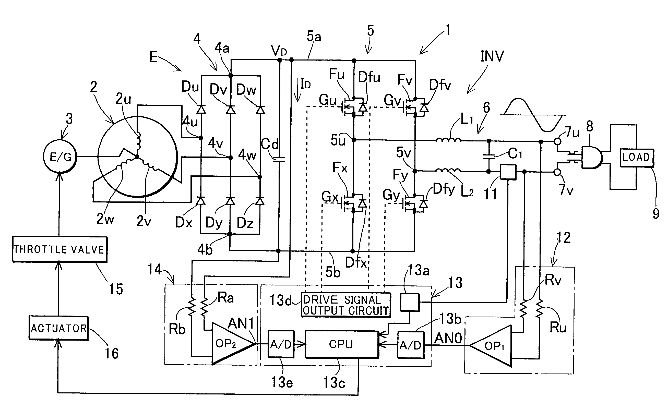
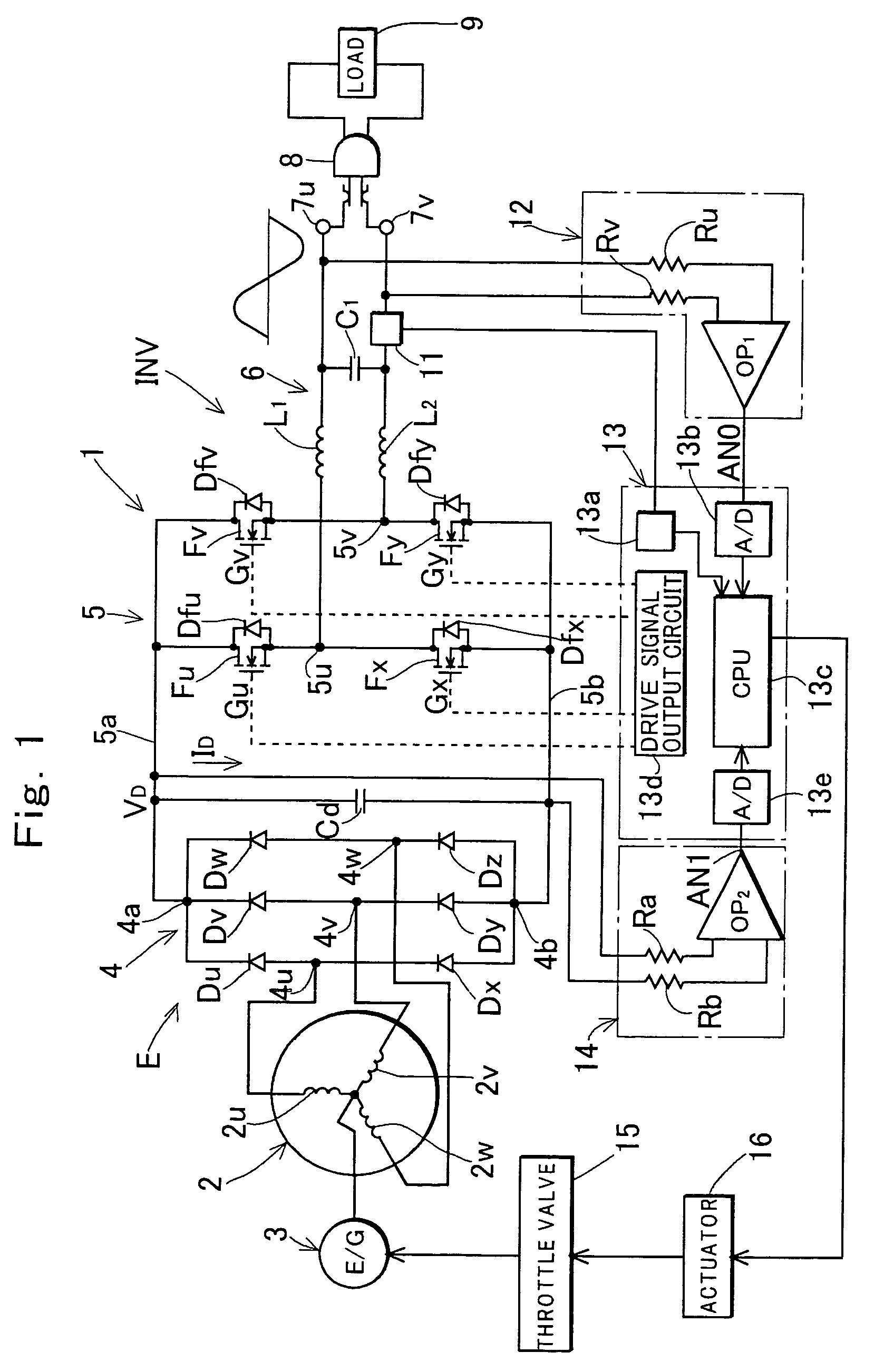
[0040]FIG. 1 shows an example of a construction of a hardware of an inverter controlled generator set 1 according to the invention. In FIG. 1, a reference numeral 2 denotes a three-phase magneto generator, and 3 denotes an engine (E / G) that drives the magneto generator 2. The magneto generator 2 includes a multi-polar magnetic rotor (not shown), and a stator having three-phase connected armature coils 2u to 2w, and the unshown magnetic rotors are mounted to a crankshaft of the engine 3.

[0041]A reference numeral 4 denotes a three-phase diode bridge full-wave rectifier constituted by diodes Du to Dw and Dx to Dz. Three-phase output terminals of the generator 2 are connected to three-phase AC input terminals 4u to 4w of the rectifier 4, and a power supply capacitor Cd is connected across DC output terminals 4a and 4b of the rectifier 4. In the shown example, a DC power source section E that uses the generator driven by the engine as a power supply to output a DC voltage is comprised of...


PUM


Abstract

A method for controlling an inverter controlled generator set which comprises a DC power source section having as a power source a generator driven by an engine and an inverter which converts an output of said DC power source section into an AC output, the method comprising a step of controlling a rotational speed of the engine so that the AC output suitable for driving a load is output from the inverter; wherein, after the engine is started, the rotational speed of the engine is controlled by a constant speed control mode for maintaining the rotational speed of the engine at a set rotational speed, and the rotational speed of the engine is increased to the set rotational speed; and wherein an operation of the inverter is started after the rotational speed of the engine reaches the set rotational speed.

Description

TECHNICAL FIELD OF THE INVENTION[0001]The present invention relates to an inverter controlled generator set comprising a DC power source section having as a power source a generator driven by an engine and an inverter which converts a DC output of said DC power source section to an AC output which is supplied to a load.BACKGROUND OF THE INVENTION[0002]An inverter controlled generator set comprises an engine, a DC power source section having as a power source a generator driven by the engine and an inverter converting an output of the DC power source section into an AC output to supply to a load as disclosed in, for example, Japanese Patent Application Laid-Open Publication No. 2001-128463.[0003]Generally, an AC generator is used as a generator driven by an engine. In this case, a DC power source section comprises the generator, a rectifier circuit rectifying an AC output of the generator and a capacitor smoothing an output of the rectifier circuit.[0004]The inverter comprises: a bri...

Claims


Application Information

Patent Timeline
Patent Type & Authority Patents(United States)
IPC IPC(8): H02J7/14H02P9/30H02P9/44F02D29/06H02M7/48H02P1/00H02P3/00H02P9/04H02P9/08
CPCH02P9/04
Inventor NAKAGAWA, MASANORIENDOU, MASAHIKOSHINBA, KAORUYAMAMOTO, KATSUMISUGISAWA, YOSHIHIRO
Owner KOKUSAN DENKI CO LTD
Why Eureka
Try Eureka