Methods and apparatus for controlling the output voltage of a switched-mode power supply

Active Publication Date: 2007-01-02
META PLATFORMS INC
View PDF4 Cites 17 Cited by
  • Summary
  • Abstract
  • Description
  • Claims
  • Application Information

AI Technical Summary

Benefits of technology

[0006]In conventional PWM the output of each phase is arranged such that each phase is activated for a length of time proportional to the desired output voltage of the power supply. In other words, the width of the pulse is modulated on each phase proportionally to the desired output voltage; a larger required output voltage resulting in a longer pulse width. However, in the present invention, higher voltage outputs are achieved by activating a larger number of phases in any particular sampling time period. Thus the approach presented in the present specification is not strictly, PWM because the width of the pulses is not chosen in proportion to the desired output voltage. This has the significant advantage that balancing of the phases is more readily achieved. One approach to such balancing, which is described in more detail below, is to rotate the phases after each sampling time period so that, for example, even if the desired output voltage of the power supply were constant, the distribution of energy across the phases would still be evenly balanced across all phases. Additionally, switching losses are reduced by reducing the number of switching transitions needed to achieve a desired output. This allows the modulation section of the power supply to operate at improved efficiency levels.

Problems solved by technology

Instead, conventional PWM “smears” the desired value across several time samples resulting in instantaneous errors even though over time the results may on average be reasonably accurate.

Method used


Image

  • Methods and apparatus for controlling the output voltage of a switched-mode power supply
  • Methods and apparatus for controlling the output voltage of a switched-mode power supply
  • Methods and apparatus for controlling the output voltage of a switched-mode power supply

Examples


Embodiment Construction

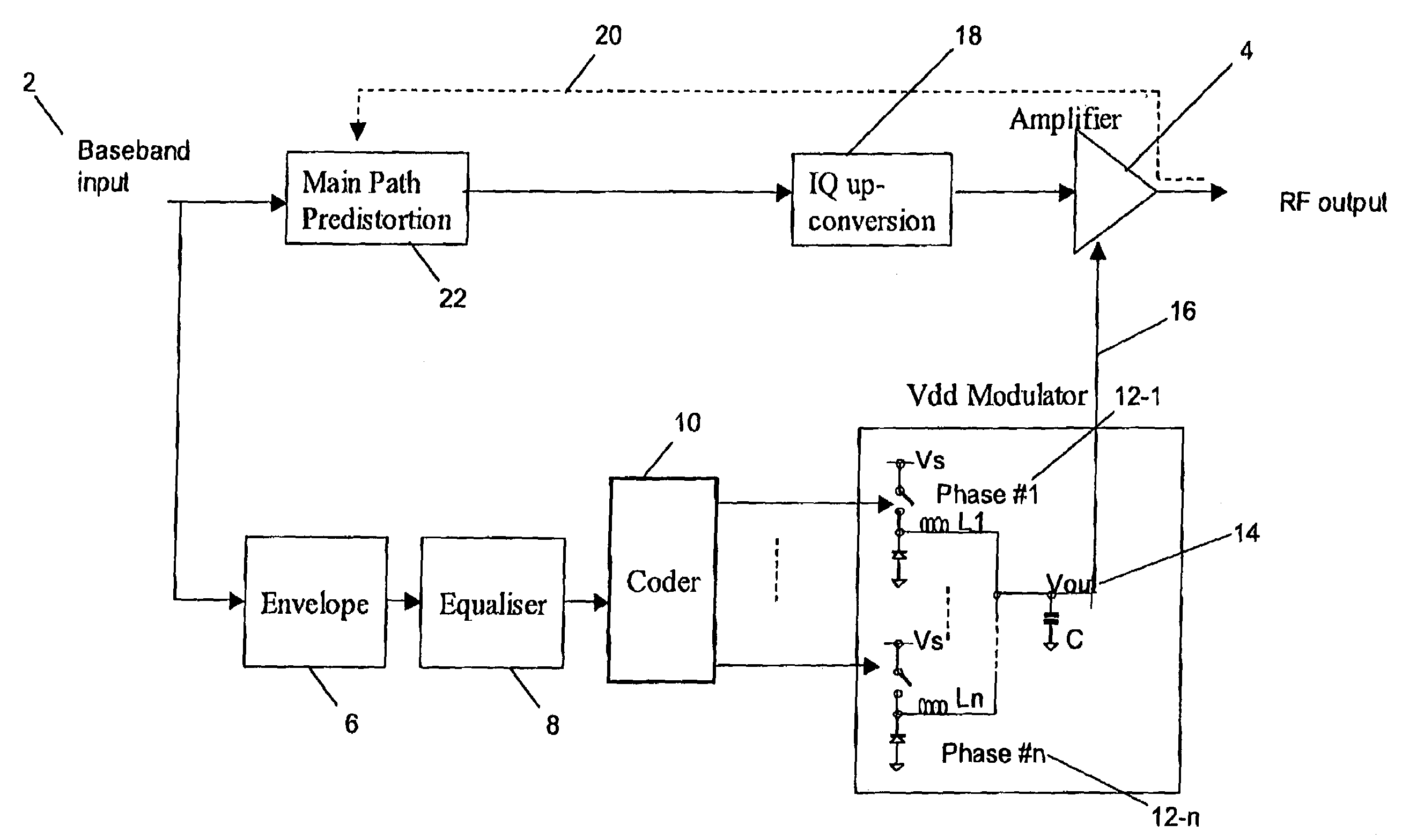
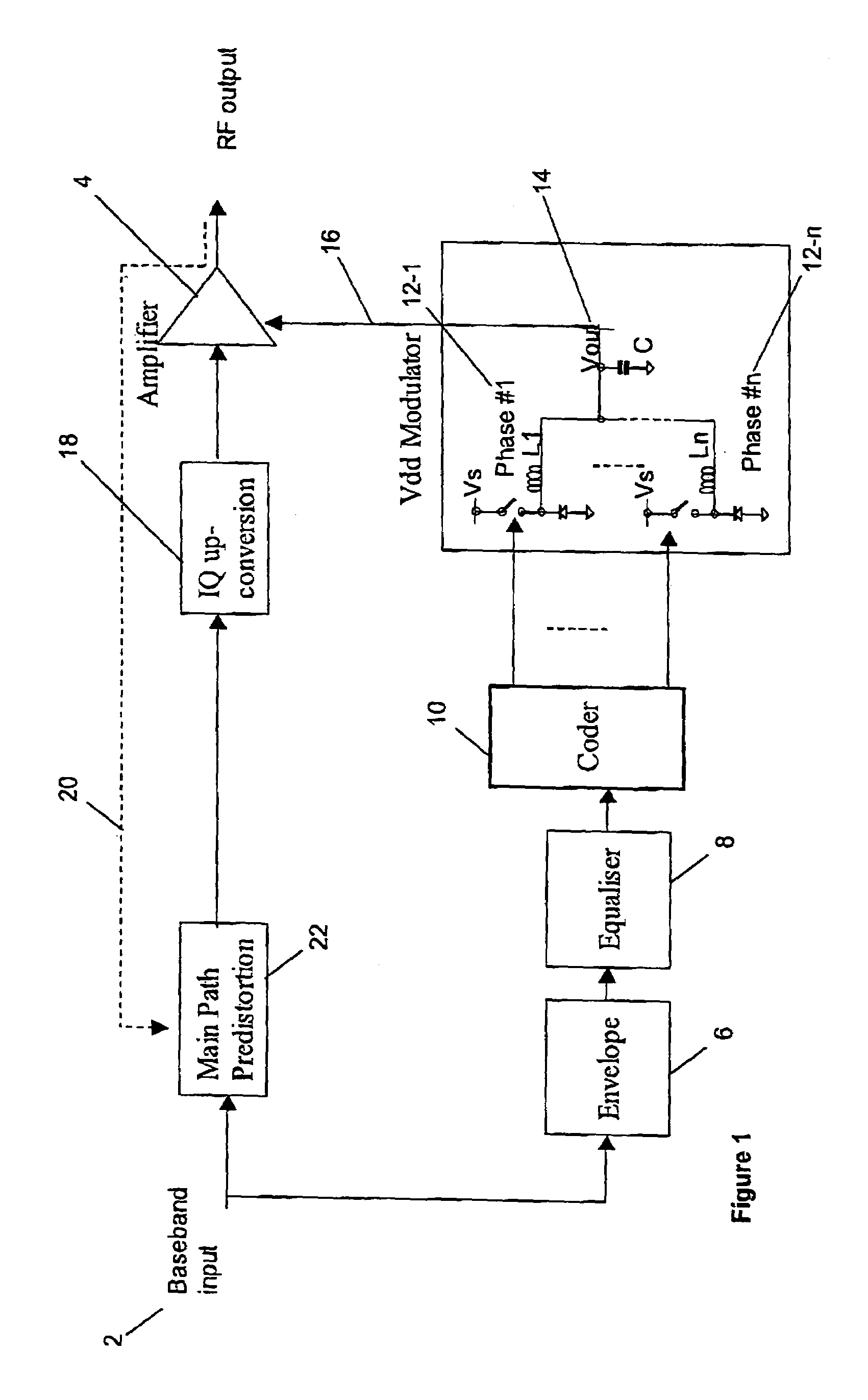
[0024]With reference to FIG. 1, a baseband input 2 receives a signal to be amplified by an RF amplifier 4. The signal typically would be a broadcast signal, for example, for a cellular base station. The baseband input is also fed to a filter 6 a which generates a signal representative of the of envelope of the baseband signal. This is equalised in equaliser 8 and then passed to a coder 10, which is described in more detail below.

[0025]The function of the coder 10 is to determine which of a plurality of switched mode power supply phases 12-1 to 12-n will be activated, summed by a summer 14, filtered and fed as a modulated power supply voltage 16 to the amplifier 4.

[0026]As is known in the art, the baseband input is passed through an IQ upconverter 18 and predistortion 20 is applied via a main path predistorter 22 in order to counteract distortions introduced by the amplifier 4.

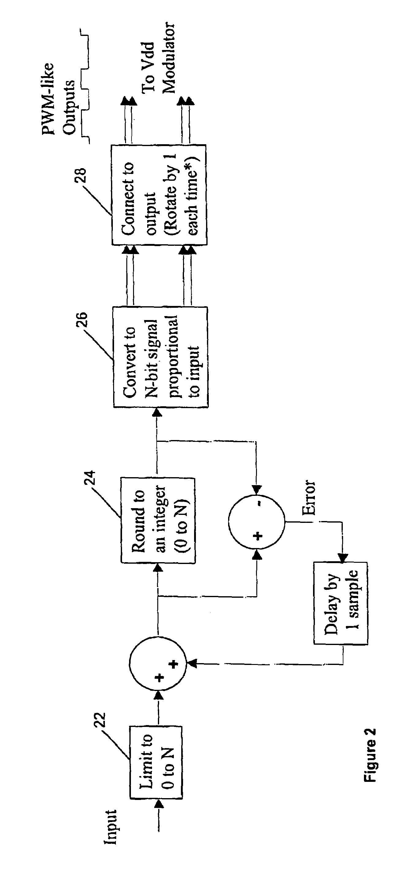
[0027]With reference to FIG. 2, the coder 10 is now described in more detail. The input to the coder 10 typi...


PUM


Abstract

Linear power amplifiers tend to be inefficient. This is a particular problem for RF amplifiers in a cellular base station. In order to improve the efficiency of such amplifiers, attempts have been made to modulate the power supply to the amplifier proportional to the envelope of the signal to be amplified. An UMTS signal requires power supply modulation at frequencies of the order of 10 to 20 megahertz. When quantization noise is taken into account, oversampling becomes desirable. However, switching power supplies at frequencies of the order of 40 or 80 or even 160 megahertz becomes difficult. By modifying the coding of phases of the power supply to be switched so that the number of phases enabled is proportional to the desired power supply output voltage rather than the length of a pulse in a time domain on any particular phase being proportional to the output voltage, dramatic improvements are achieved in switching losses, balance between phases and accurate tracking of the input signal. Rotation of switching across the phases achieves good balance and by jittering or randomizing the rotation, switching noise may be moved out of band.

Description

TECHNICAL FIELD[0001]This invention relates to methods and apparatus for controlling the power supply voltage in a multi-phase, switched-mode power supply, to software for controlling a switched mode power supply, to a power supply unit, to an RF amplifier and to a cellular base station. Although described below in connection with RF power amplifiers, it will be appreciated by the person skilled in the art that the power supply control techniques disclosed in the present specification have general applicability to fields outside the control of RF amplifier power supply control.BACKGROUND OF THE INVENTION[0002]It is desirable, particularly in cellular base station applications, to be able to accurately and quickly control the power supply voltage provided to a radio frequency (RF) amplifier. Linear power amplifiers are fundamentally inefficient. This means that large, expensive RF power transistors are required and that these transistors require large heat sinks. This increases the s...

Claims


Application Information

Patent Timeline
IPC IPC(8): H03F3/38
CPCH03F1/0227H03F1/3247H03F2200/504H03F2200/336H03F2200/351H03F2200/102
Inventor BOOTH, ANDREWO'FLAHERTY, MARTINDOLMAN, GRAHAM
Owner META PLATFORMS INC
Why Eureka
Try Eureka