Cut of piezoelectric oscillator, piezoelectric oscillator, and piezoelectric device

a piezoelectric oscillator and piezoelectric technology, applied in the direction of device material selection, generator/motor, impedence network, etc., can solve the problem of machining errors, spurious mode coupling, and unsatisfactory modes, etc., to improve the stability of frequency against machining errors, stable frequency, cost reduction

Active Publication Date: 2007-01-02
SEIKO EPSON CORP
View PDF7 Cites 9 Cited by
  • Summary
  • Abstract
  • Description
  • Claims
  • Application Information

AI Technical Summary

Benefits of technology

[0016]A piezoelectric resonator according to the present invention consists of any one of the above-described cuts of a piezoelectric resonator and can provide improved stability of frequency against machining errors of the longer and shorter sides of a blank. In addition, a piezoelectric resonator having a stable frequency in a wide temperature range of from −25° C. to +100° C. is obtained.
[0017]Also, a piezoelectric device according to the present invention is cha

Problems solved by technology

However, more spurious modes (undesired modes) having other modes of vibration are produced than the conventional AT-cut resonator.
Therefore, if the frequency comes too close to that of the main modes, both vibrations are mechanically coupled, causing jumps in the frequency of the main

Method used


Image

  • Cut of piezoelectric oscillator, piezoelectric oscillator, and piezoelectric device
  • Cut of piezoelectric oscillator, piezoelectric oscillator, and piezoelectric device
  • Cut of piezoelectric oscillator, piezoelectric oscillator, and piezoelectric device

Examples


Embodiment Construction

[0031]The preferred embodiments of cut of a piezoelectric resonator, piezoelectric resonator, and piezoelectric device according to the present invention are described in detail with reference to the accompanying drawings.

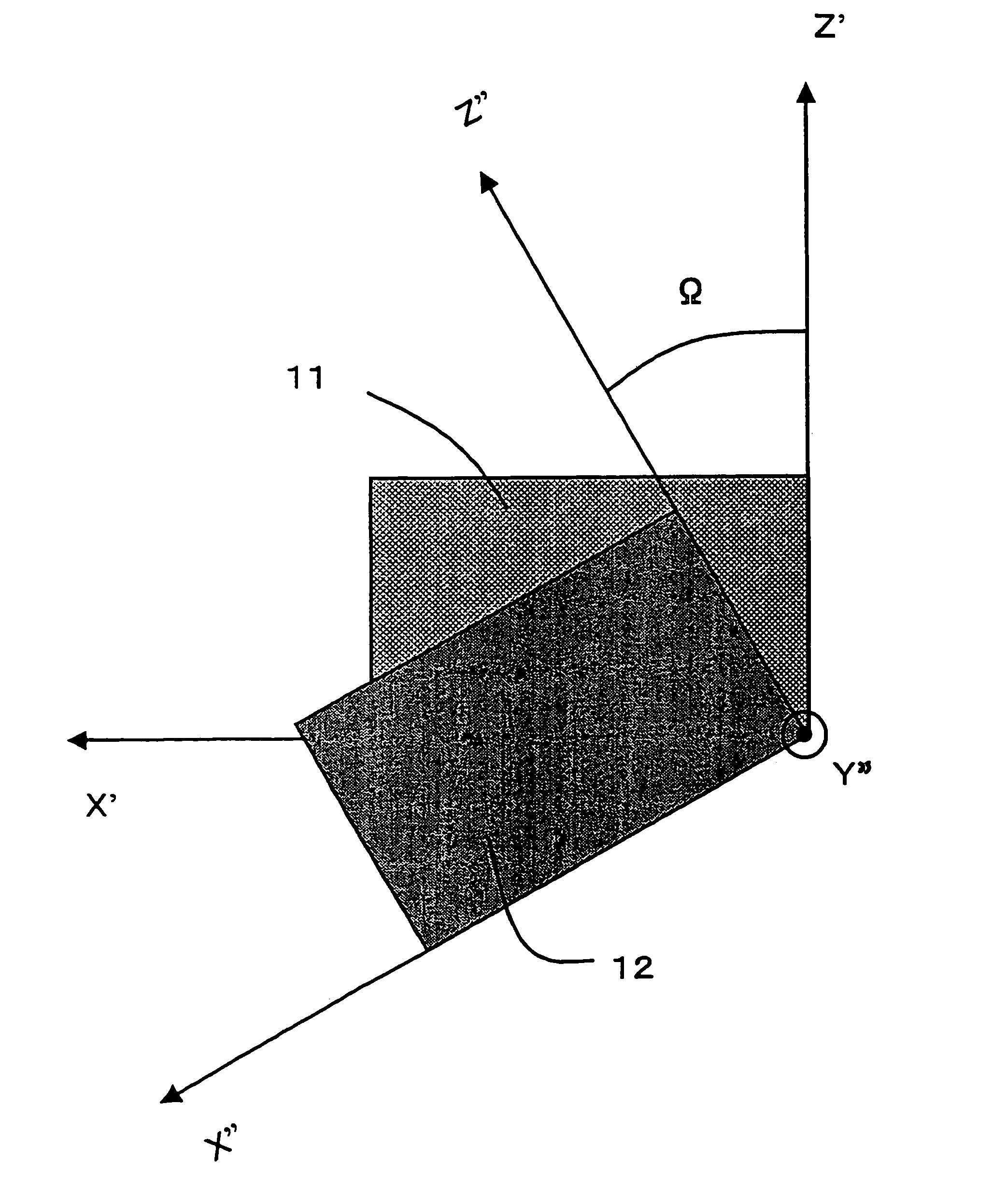
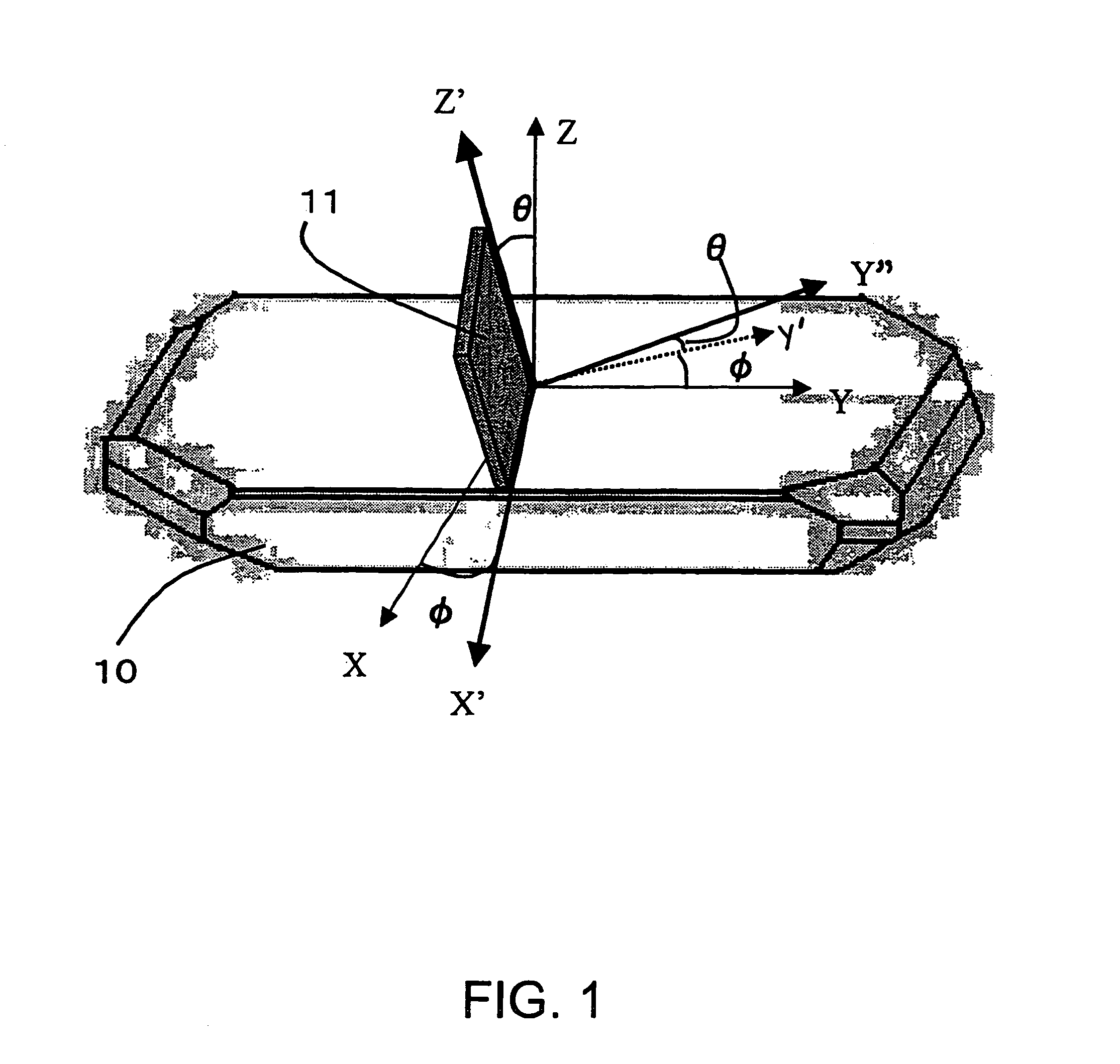
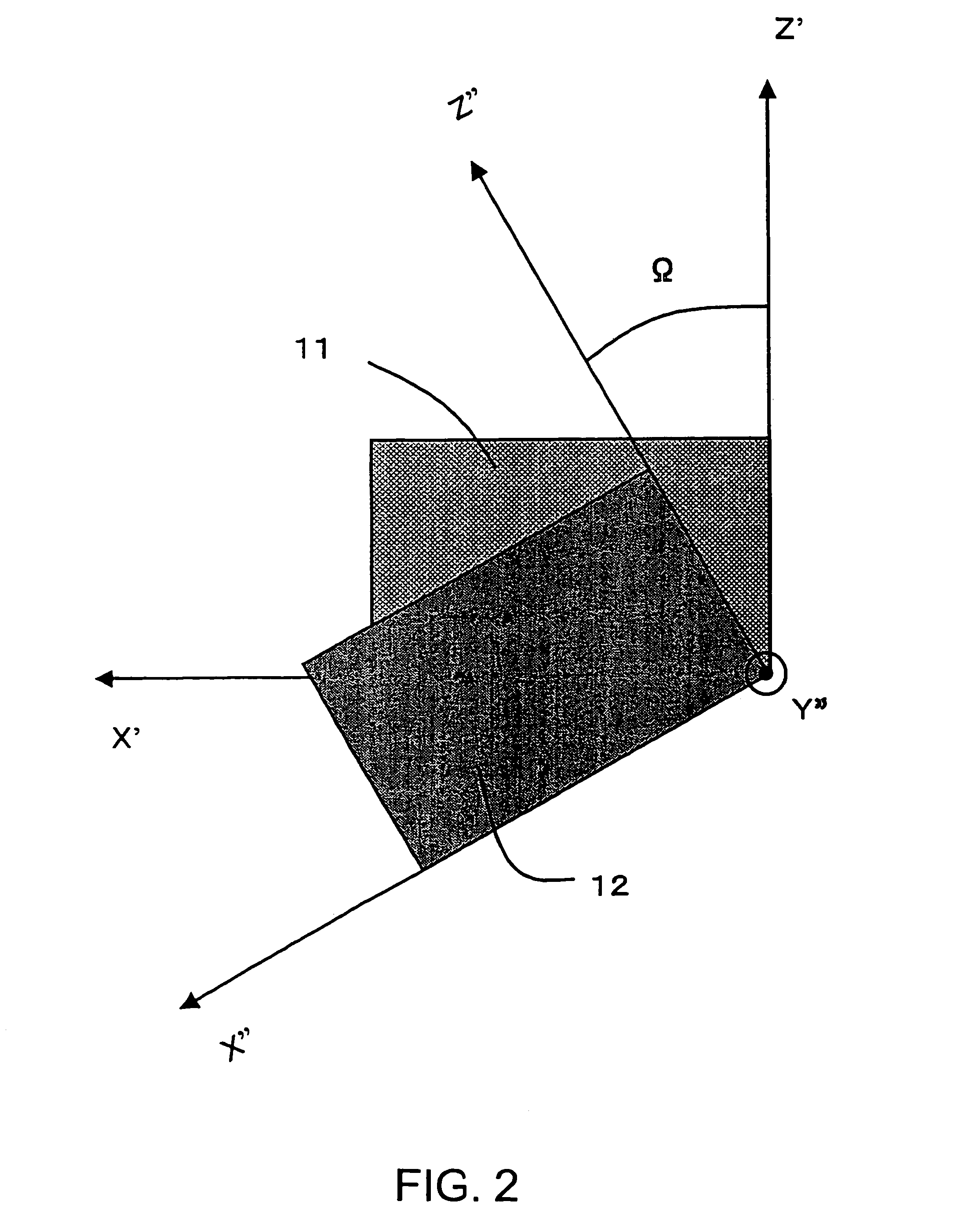
[0032]FIGS. 1 and 2 are views illustrating cut angles of quartz for obtaining a cut of quartz resonator that is a cut of a piezoelectric resonator according to the present invention. In FIG. 1, three axes of a quartz crystal 10 crossing perpendicularly to each other, i.e., electric axis, mechanical axis crossing perpendicularly to the electric axis, and optic axis crossing perpendicularly to those axes are taken as X axis, Y axis, and Z axis, respectively. With respect to the cut angles of the doubly-rotated cut-angled quartz plate (quartz substrate) 11 defined in the present invention, an X′ axis obtained by rotating the X axis about the Z axis with merely φ in a clockwise direction is first established. The plate has sides parallel to the X′ axis. Furthermore, th...


PUM


Abstract

A cut of a piezoelectric resonator uses a quartz plate having an electric axis, mechanical axis, and optic axis on an X axis, Y axis, and Z axis, respectively. An X′ axis is set by rotating the X axis with an angle of 3–30 degrees in a clockwise direction about the Z axis. A Z′ axis is set by rotating the Z axis in the clockwise direction with an angle of 33–36 degrees about the X′ axis. The quartz plate has sides parallel to the X′ axis and Z′ axis, respectively. Furthermore, the plate has sides parallel to X″ axis and Z″ axis, respectively, which have been rotated in the clockwise direction with angles of from −35 degrees to −2 degrees about a Y′ axis that is the thickness direction of the cut of the piezoelectric resonator.

Description

RELATED APPLICATIONS[0001]This application claims priority to Japanese Patent Application No. 2003-076245 filed Mar. 19, 2003 which is hereby expressly incorporated by reference herein in its entirety.BACKGROUND OF THE INVENTION[0002]1. Technical Field[0003]The present invention relates to a cut of a resonator making use of a piezoelectric effect and, more particularly, to a cut of a piezoelectric resonator, piezoelectric resonator, and piezoelectric device using a so-called new cut quartz plate.[0004]2. Related Art[0005]As various kinds of electronic devices have been advanced and communication systems have evolved in recent years, piezoelectric devices typified by piezoelectric resonators have been used frequently. Especially, quartz acting as a piezoelectric material has enjoyed wide acceptance in piezoelectric devices, because high frequencies are obtained and stable frequency characteristics are provided. AT-cut quartz plates (hereinafter simply abbreviated AT-cut plates) have ...

Claims


Application Information

Patent Timeline
IPC IPC(8): H03B5/32H03H9/19H01L41/09H01L41/18H03H9/02
CPCH03H9/02834H03H9/02551
Inventor TANAKA, MASAKO
Owner SEIKO EPSON CORP
Why Eureka
Try Eureka