

Modulation apparatus/method, demodulation apparatus/method and program presenting medium
a technology of demodulation apparatus and program presenting medium, which is applied in the direction of instruments, recording signal processing, code conversion, etc., can solve the problems of adversely affecting the minimum run time, the prone to distortion of recording wave train, and the inability to record consecutive minimum marks (2t)
- Summary
- Abstract
- Description
- Claims
- Application Information
AI Technical Summary
Benefits of technology
Problems solved by technology
Method used
Image

Examples
Embodiment Construction
[0002]1. Technical Field of the Invention
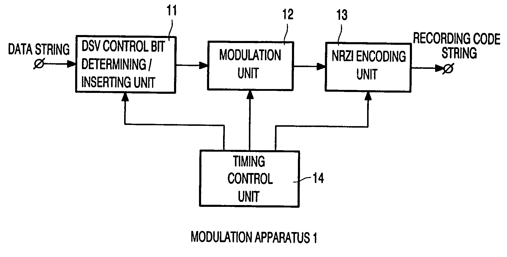
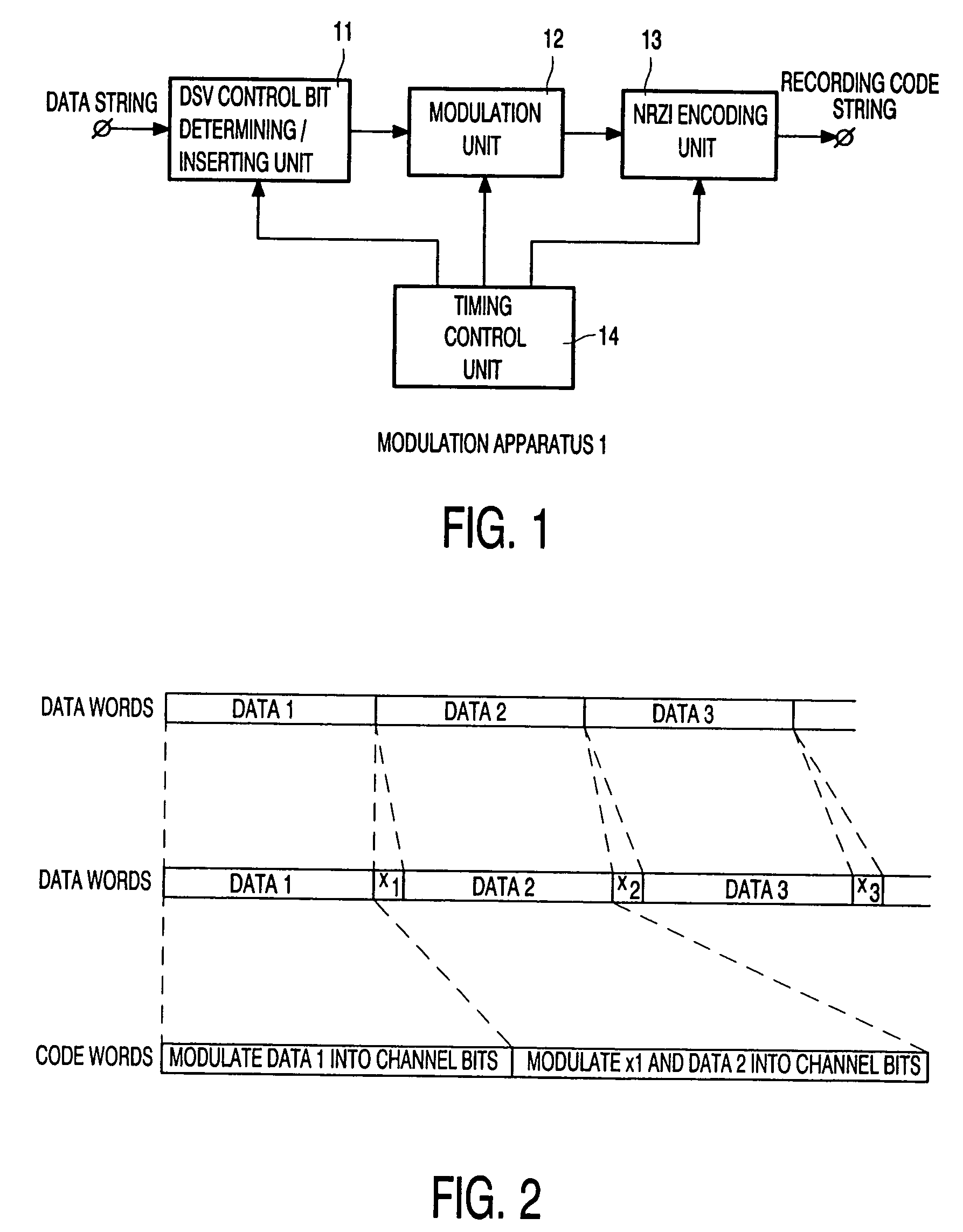
[0003]In general, the present invention relates to a modulation apparatus and a modulation method, a demodulation apparatus and a demodulation method as well as a program presenting medium. More particularly, the present invention relates to a preferable modulation apparatus and a preferable modulation method, a preferable demodulation apparatus and a preferable demodulation method as well as a preferable program presenting medium used in operations to record data onto a recording medium at a high recording density and playback data recorded in a recording medium at a high recording density.
[0004]2. Prior Art
[0005]When data is transmitted through a transmission line or recorded onto a recording medium such as a magnetic disc, an optical disc or a magneto-optic disc, the data is modulated into code matching the transmission line or the recording medium prior to the transmission or recording. As a technique of modulation, block encoding is know...
PUM
| Property | Measurement | Unit |
|---|---|---|
| length | aaaaa | aaaaa |
| run length | aaaaa | aaaaa |
| variable length | aaaaa | aaaaa |
Abstract
Description
Claims
Application Information