Compact, head-mountable display device with suspended eyepiece assembly

a display device and eyepiece technology, applied in the field of compact head-mounted display devices with suspended eyepiece assemblies, can solve the problems of high degree of occlusion of the user's field of view, distortion, use of non-axial optics, etc., and achieve the effect of simple mounting system

Inactive Publication Date: 2007-01-02
GOOGLE LLC
View PDF180 Cites 219 Cited by
  • Summary
  • Abstract
  • Description
  • Claims
  • Application Information

AI Technical Summary

Benefits of technology

[0007]The present invention provides a light weight, compact head-mountable display device that combines an image relay system and mechanical support with a simple mounting system that can be applied to eyeglasses or other head gear. The display device comprises suspending an eyepiece in front of the eye and transmitting by free space projection an image from an electronic display mounted near the temple. The device is also suitable as an interface to computers, personal digital assistants, and cellular telephones.
[0009]This invention overcomes the limitations of the previous eyepiece approaches by employing designs that reduce off-axis distortion. These approaches also permit reduction of weight by reducing the number of optical elements needed for distortion correction. In one preferred embodiment of this invention, a display mounted near the temple of a user, combined with a magnifying eyepiece suspended in front of the eye of the user makes viewing of the image on the display possible without the weight of a transparent mechanical support. The eyepiece may be of the see-around type or the see-through type. The use of free-space projection to the eyepiece reduces the weight and cost of the system. Since the system in this embodiment is axial, no non-axial aberration is introduced.
[0010]In a second preferred embodiment, the eyepiece utilizes a form of Mangin mirror, which, through its refractive properties, reduces the angle of incidence on the focusing surface of the mirror. The display and projection optics are located near the temple of the user, and the image is relayed through free space to the mirror. The mirror itself is suspended by a wire or other fixture. The weight and cost of the system are reduced over the prior art, and the aberration from off-axis projection is reduced by the modified Mangin mirror.

Problems solved by technology

Perera describes a display mounted on eyeglasses, the limitation of which is the high degree of occlusion of the user's field of view beyond the display, and the use of non-axial optics, which introduces distortion.
These approaches also highly limit the user's view of the surroundings.
Consequently, such systems block a portion of the user's visual field, and also obscure the user's face.
A limitation is the additional weight of the clear optical supporting section.
This approach, and others like it, suffers from distortion resulting from the off-axis design.

Method used


Image

  • Compact, head-mountable display device with suspended eyepiece assembly
  • Compact, head-mountable display device with suspended eyepiece assembly
  • Compact, head-mountable display device with suspended eyepiece assembly

Examples


Embodiment Construction

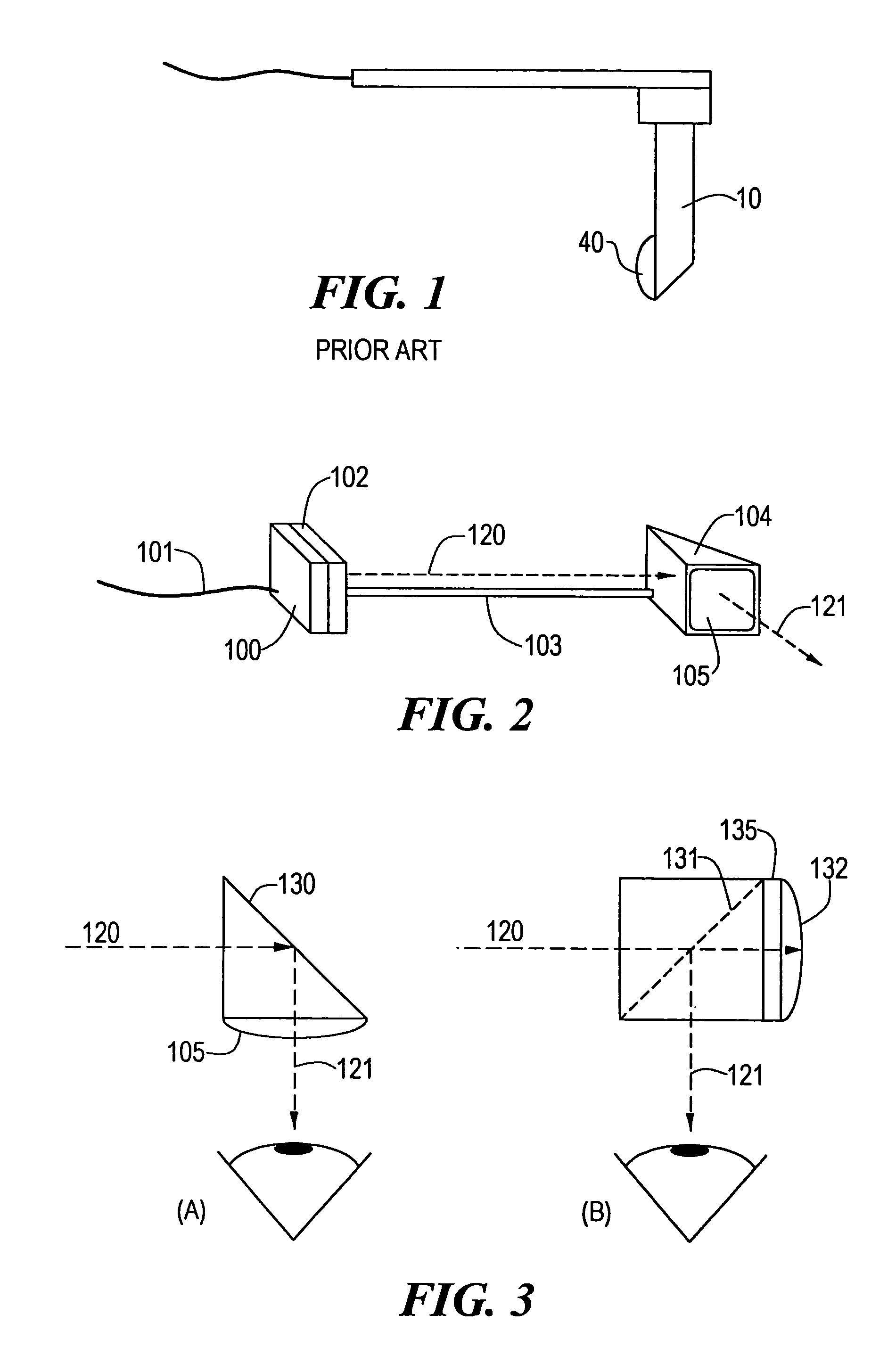
[0025]A first embodiment of the invention is shown in FIG. 2. Signals are conveyed by cable 101 to a projection system having a display 102, which may be an electroluminescent display, a liquid crystal display (LCD), a field emission display, a cathode ray tube, or other miniature display. If the display is a transmissive LCD, of the type manufactured by Kopin Corporation, of Taunton, Mass., it is provided with a backlight 100. In such a case rays from the backlight illuminate the backside of display 102 and emerge from the front after having been modulated to form an image. In the case of an emissive display, such as an active matrix electroluminescent display of the type manufactured by Planar Corporation, Beaverton, Oreg., no backlight is required.

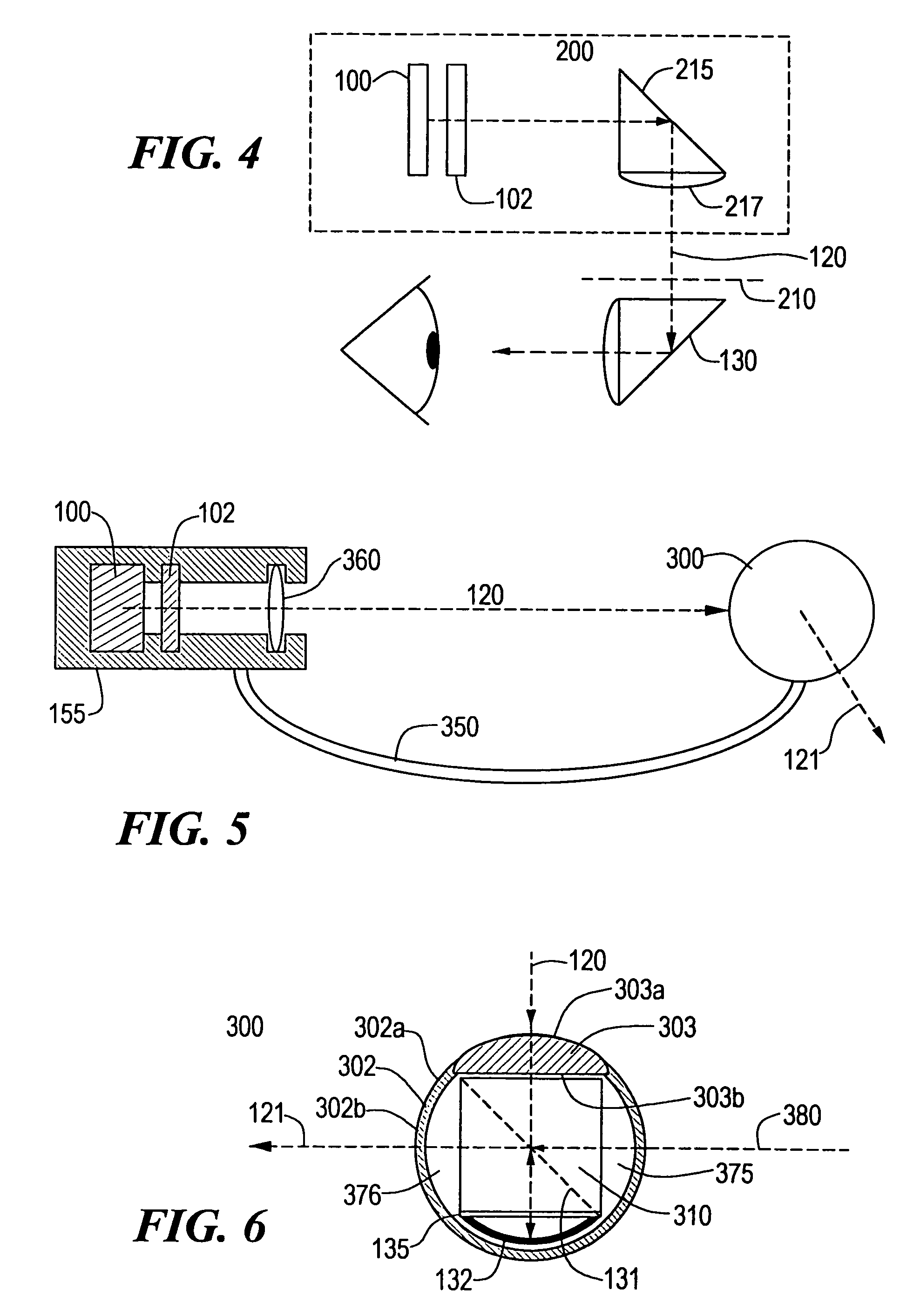
[0026]Referring to FIG. 2, a ray 120 emerges from the display 102 and propagates on an optical path to a eyepiece assembly 104. The eyepiece assembly is suspended at one end of a support fixture 103. The support fixture 103 is attached ...


PUM


Abstract

A compact, lightweight, head-mountable display device is provided for transmitting an image to a user's eye. The device includes a projection system including a display attached at one end to a head-mountable support fixture. An eyepiece assembly is attached to a second end of the support fixture. The support fixture maintains the projection system and the eyepiece assembly in alignment along an optical path through free space between the projection system and the eyepiece assembly, with the projection system disposed to transmit the image on the optical path and the eyepiece assembly disposed to receive the image from the projection system and to direct the image to the user's eye.

Description

CROSS REFERENCE TO RELATED APPLICATIONS[0001]Applicant claims priority under 35 U.S.C. § 119(e) of U.S. Provisional Application No. 60 / 140,340, filed Jun. 21, 1999, entitled “Light Weight, Compact Eyepiece on a Post,” and No. 60 / 140,707, filed on Jun. 24, 1999, entitled “Light Weight, Compact Eyepiece on A Post,” the disclosures of which are incorporated by reference herein.STATEMENT REGARDING FEDERALLY SPONSORED RESEARCH OR DEVELOPMENT[0002]N / ABACKGROUND OF THE INVENTION[0003]There are many examples of displays mounted on the head, sunglasses, eyeglasses and the like (for example Perera, U.S. Pat. No. 4,867,551). Perera describes a display mounted on eyeglasses, the limitation of which is the high degree of occlusion of the user's field of view beyond the display, and the use of non-axial optics, which introduces distortion. Other companies, such as VirtualVision, provide displays that are suspended by a cable, gooseneck fixture or other mechanical support in front of one or both o...

Claims


Application Information

Patent Timeline
Patent Type & Authority Patents(United States)
IPC IPC(8): G09G5/00G03H1/00
CPCG02B27/0172G02B5/30G02B2027/0178G02B2027/011
Inventor SPITZER, MARK B.
Owner GOOGLE LLC
Why Eureka
Try Eureka