Method for detecting reverse rotation for internal combustion engines
a technology of internal combustion engine and reverse rotation, which is applied in the direction of machines/engines, electrical control, instruments, etc., can solve the problems of engine rotation in reverse, sampling of crankshaft signals, and unsatisfactory reverse rotation of crankshafts
- Summary
- Abstract
- Description
- Claims
- Application Information
AI Technical Summary
Benefits of technology
Problems solved by technology
Method used
Image
Examples
Embodiment Construction
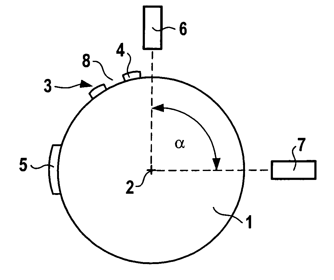
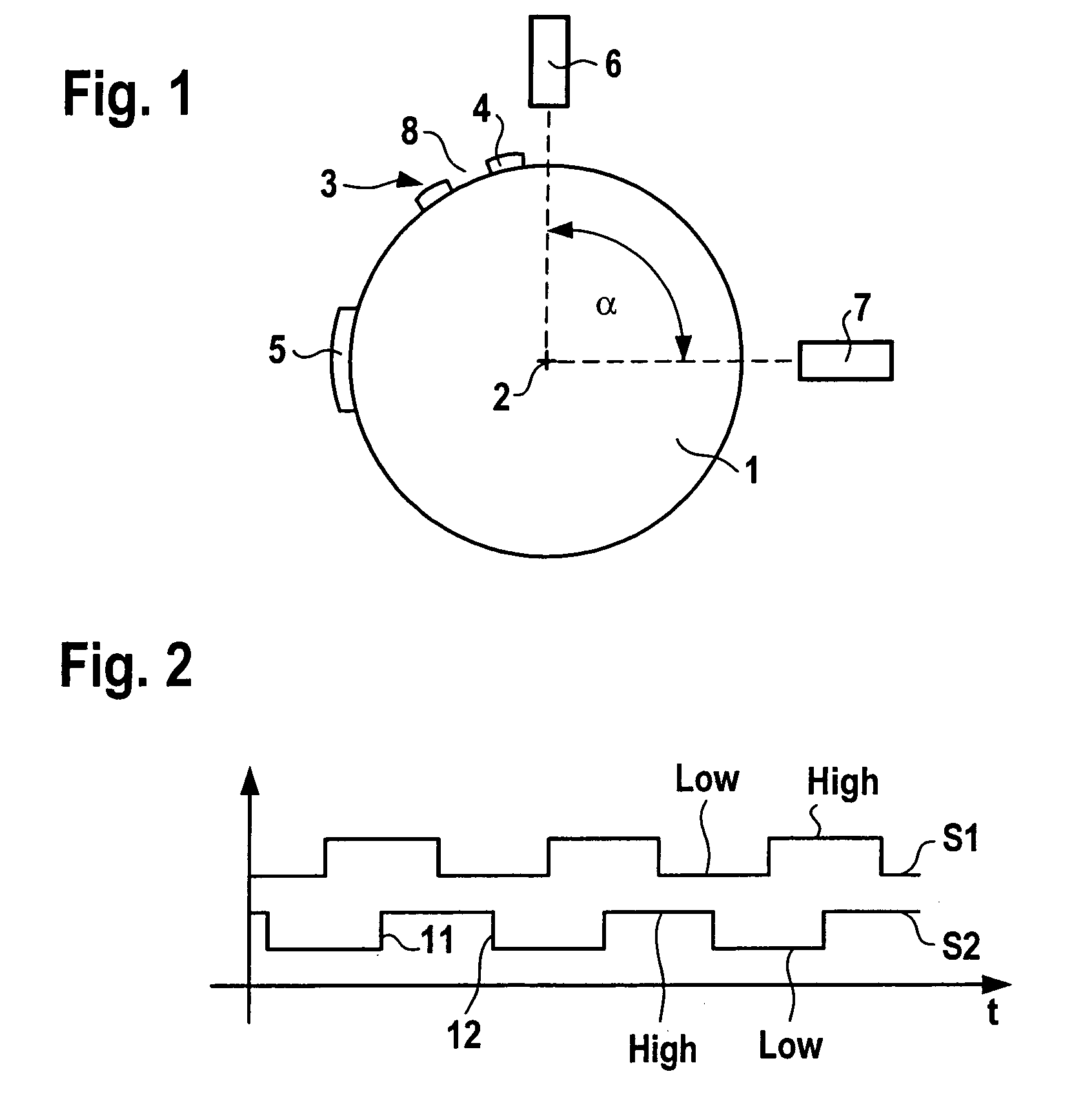
[0020]FIG. 1 shows a schematic drawing of a sensor disk 1, which is situated directly on a crankshaft or camshaft, for example, or is indirectly connected to the camshaft with the aid of transmission elements for rotation. Sensor disk 1 rotates about an axis 2. Markings 3 are situated on the outer periphery of sensor disk 1. The markings include, for example, teeth 4, which are situated equidistant over the outer periphery of sensor disk 1. Tooth spaces 8 are situated between teeth 4. An additional marking 5, for example, as shown here in the form of a tooth 4 having double the width or in the form of a larger tooth space between two teeth 4 or the like marks an established zero position of the crankshaft. Each tooth extends over an angle of approximately 3°; each tooth space extends over an angle of 3°. Therefore, tooth 4 and the adjacent tooth space 8 extend over an angle of approximately 6°.
[0021]A first sensor 6 and a second sensor 7 are situated on sensor disk 1. Sensors 6, 7 a...
PUM
 Abstract
Description
Claims
Application Information
 - R&D
- Intellectual Property
- Life Sciences
- Materials
- Tech Scout
- Unparalleled Data Quality
- Higher Quality Content
- 60% Fewer Hallucinations
Browse by: Latest US Patents, China's latest patents, Technical Efficacy Thesaurus, Application Domain, Technology Topic, Popular Technical Reports.
© 2025 PatSnap. All rights reserved.Legal|Privacy policy|Modern Slavery Act Transparency Statement|Sitemap|About US| Contact US: help@patsnap.com


