Method of manufacturing a color filter

Inactive Publication Date: 2007-01-09
EASTMAN KODAK CO
View PDF15 Cites 38 Cited by
  • Summary
  • Abstract
  • Description
  • Claims
  • Application Information

AI Technical Summary

Problems solved by technology

As is known in the art, these processes are not adapted to generate patterned layers of thermally unstable color filter materials.
This method is disadvantaged because the ink compositions, which include the color filter material, have high solvent concentrations which enables the ejection of the ink composition using conventional inkjet printers.
Additionally, the color filter materials used will not always dissolve or solubilize in commonly available solvents.
This can necessitate the use of exotic solvents that are environmentally harmful and/or expensive.
There is a problem with this method in that the free-jet expansion of the supercritical fluid solution results in a non-collimated/defocused spray that cannot be used to create high resolution patterns on a receiver.
Furthermore, Smith does not teach the use of a mask to create high resolution patterns on a receiver.
There is a problem with this technology in that the marking material and propellant stream are two different entities and the propellant is used to impart kinetic energy to the marking material.
This non-colloidal ballistic aerosol, which is a combination of the marking material and the propellant, is not thermodynamically stable/metastable.
As such, the marking material is prone to settling in the propellant stream which, in turn, can cause marking material agglomeration, leading to discharge device obstruction and poor control over marking material deposition.
This method is disadvantaged because deposition using a feathered spray requires that the wafer surface be prepatterned prior to deposition.
Hence, direct patterning of the wafer surface is not possible because of the diverging profile (feathered) of the spray.
Additionally, a wafer surface that has not been prepatterned cannot be patterned using this method.
However, when the surface is nonplanar, difficulties can be encountered in depositing and cleaning off the photoresist material, necessitating the use of shadow masks or ste

Method used


Image

  • Method of manufacturing a color filter
  • Method of manufacturing a color filter
  • Method of manufacturing a color filter

Examples


embodiment i

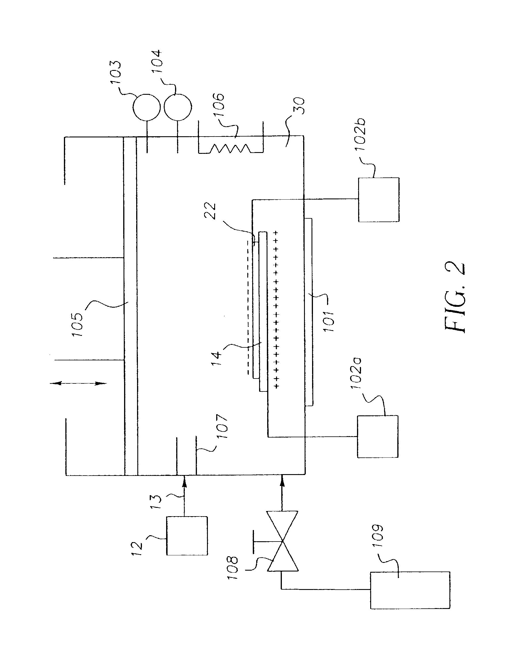
[0056]Referring to FIG. 2, controlled environment 30 is designed for use at extremes of pressure. Incorporated in the controlled environment 30 is a pressure modulator 105. The pressure modulator 105, as shown, resembles a piston. This is for illustration only. Skilled artisans will also appreciate that pressure modulator 105 could also be a pump or a vent used in conjunction with an additional pressure source. An example of an additional pressure source is the source 109 of compressed fluid. This source 109 is modulated with a flow control device or valve 108 to enable color filter material to enter the deposition chamber 30 via a fluid delivery path 13. The pressure inside the deposition chamber 30 is carefully monitored by a pressure sensor 103 and can be set at any pressure less than that of the delivery system 12 (including levels of vacuum) to facilitate precipitation / aggregation. In addition, the deposition chamber 30 is provided with temperature sensor 104 and temperature mo...

embodiment ii

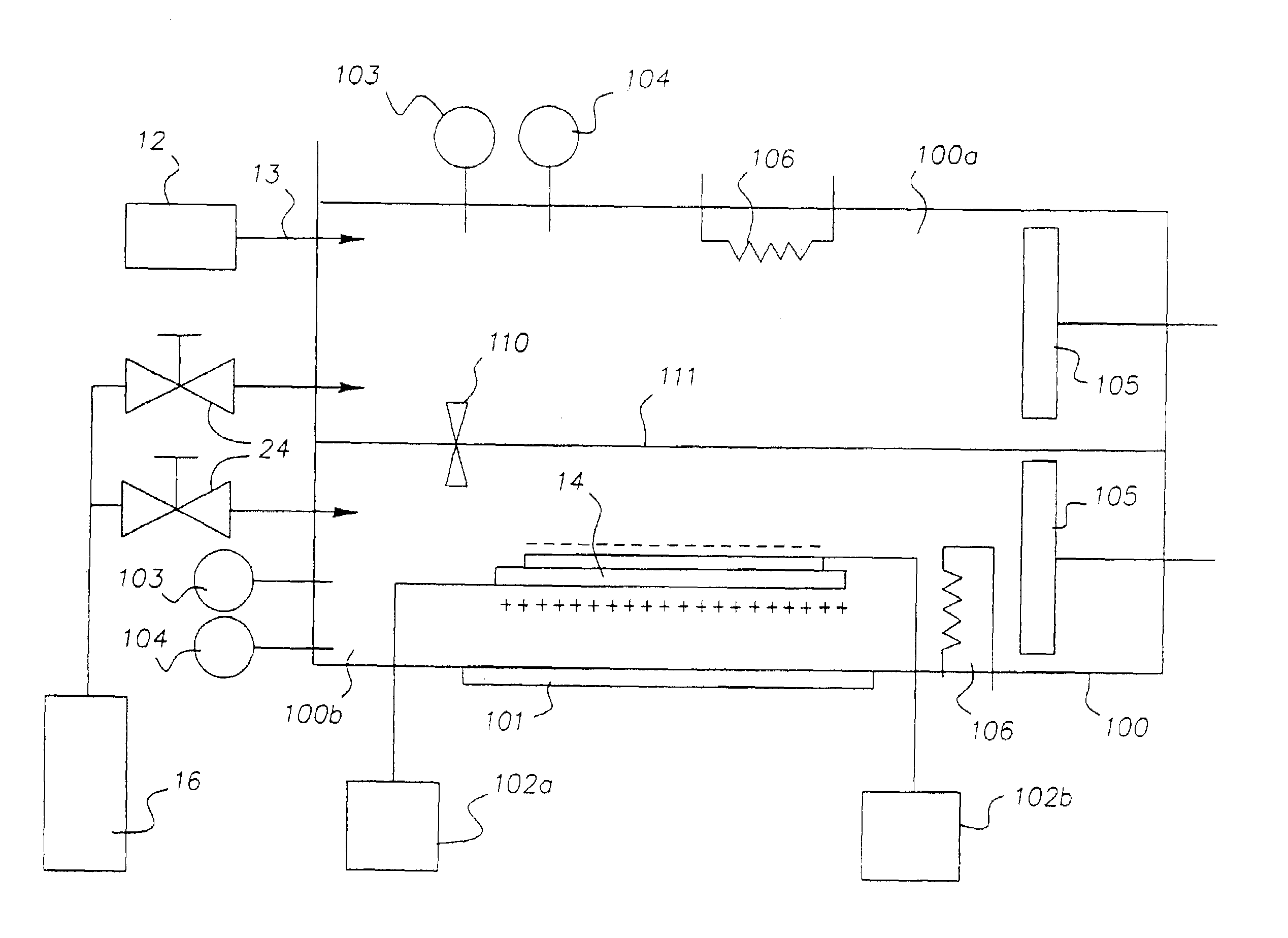
[0061]Turning now to FIG. 5, another embodiment of deposition chamber 100, contemplated by the invention, is shown. It contains many of the same features previously described in the discussion of FIG. 2, with the addition of a medium 111 which divides the deposition chamber 100 into a preparation sub-chamber 100a and a deposition sub-chamber 100b. The materials in these sub-chambers 100a, 100b are allowed to flow through controllable dual chamber interface valve 110. Each sub-chamber 100a, 100b is configured with independent control of pressure and temperature through the use of pressure sensors 103, temperature sensors 104, pressure modulators 105, and temperature modulators 106. The preparation sub-chamber 100a differs from the formulation reservoir 18 (FIG. 1) in that the color filter material 40 can be (but is not necessarily) precipitated. The addition of a preparation sub-chamber 100a to the system allows for a potentially large volume of prepared deposition material to be rea...

embodiment iii

[0062]In FIG. 6, a simplified deposition chamber 200 is illustrated. In this embodiment, no provision is made for maintaining a pressure above that of ambient. Many of the other features described in FIGS. 2 and 5 are still possible, but by no longer requiring the deposition chamber 200 to support an elevated pressure, certain additional advantages can be realized. For example, the substrate 14 no longer is required to be contained in deposition chamber 200. This is illustrated in FIG. 6 by showing a moving substrate in the form of a web 120 that is transported by conveyors 121. In such a system, it is possible to perform continuous coating operations. In this case, a separate mask would likely not be used except for the case of a step and repeat process. Rather, a mask integral to the substrate, as previously described, is the preferred method of achieving patterned deposition. Alternatively, a similar approach, illustrated in FIGS. 2 and 5, could be used also without need for acce...


PUM


Abstract

A method of forming a color filter is provided. The method includes providing a mixture of a color filter material and a compressed fluid; providing at least a partially controlled environment for retaining a substrate, the at least partially controlled environment being in fluid communication with the mixture of the color filter material and the compressed fluid; providing a shadow mask in close proximity to the substrate retained in the at least partially controlled environment; and chargably releasing the mixture of the color filter material and the compressed fluid into the at least partially controlled environment, wherein the color filter material becomes free of the compressed fluid prior to contacting the substrate at locations defined by the shadow mask thereby forming a patterned deposition on the substrate.

Description

CROSS REFERENCE TO RELATED APPLICATIONS[0001]This application is a continuation-in-part of U.S. patent application Ser. No. 10 / 313,587, filed Dec. 6, 2002 now U.S. Pat. No 6,790,483 and assigned to the Eastman Kodak Company.[0002]This application is related to Ser. No. 10 / 313,549 filed Dec. 6, 2002; and assigned to the Eastman Kodak Company.FIELD OF THE INVENTION[0003]This invention relates generally to deposition from compressed fluids and, more particularly, to patterned deposition from compressed fluids onto suitable substrates with the use of masks.BACKGROUND OF THE INVENTION[0004]Color filters and the methods used to manufacture color filters are known. Color filter producing methods include techniques that deposit color filter material onto a prepatterned substrate. These techniques include, for example, vapor deposition, spin-coating, and thermal deposition (see, for example, U.S. Pat. No. 5,874,188, issued to Roberts et al., on Feb. 23, 1999).[0005]Other methods of manufactu...

Claims


Application Information

Patent Timeline
IPC IPC(8): B05D5/06B05D1/32B05D1/02B05D1/04B05D1/06B05D1/12G02B5/22
CPCB05D1/06G02B5/223B05D1/12B05D1/025B05D1/04B05D1/32B05D2401/90
Inventor SADASIVAN, SRIDHARJAGANNATHAN, RAMESHJAGANNATHAN, SESHADRIMEHTA, RAJESHNELSON, DAVID J.IRVIN, JR., GLEN C.
Owner EASTMAN KODAK CO
Why Eureka
Try Eureka