Element for electromagnetic shielding and method for manufacturing thereof

a technology of electromagnetic shielding and elements, applied in the direction of magnetic recording, printed circuit aspects, non-conductive materials with dispersed conductive materials, etc., can solve the problems of difficult manufacturing, difficult to provide more complicated designs of elements, and relatively expensive particles that provide the electrical conductivity of elements, so as to reduce the compression force, reduce the need for particle further reduction, and reduce the effect of electrical conductivity

Inactive Publication Date: 2007-01-09
NOLATO SILIKONTEKNIK
View PDF8 Cites 8 Cited by
  • Summary
  • Abstract
  • Description
  • Claims
  • Application Information

AI Technical Summary

Benefits of technology

[0023]This results in an improved method for manufacturing an element for electromagnetic shielding. Owing to the fact that the particles are oriented by applying a magnetic field, the electrical conductivity of the element is improved. More specifically, the particles will be arranged in rows along the field lines of the magnetic field. It will thus be possible to provide a given conductivity with a reduced amount of particles. Since the cost of said particles constitutes a main part of the total cost of material for the element, this reduced need for particles results in a considerable saving in costs. An element with a reduced particle content requires also a lower compression force. The reason is that the particles act to reinforce the material of the element. Thus, a reduced particle content results in reduced reinforcement.
[0025]According to a preferred embodiment of the inventive method, the magnetic field applied across the bead is given such a strength and / or duration that the particles, during their orientation in the same direction as the magnetic field, affect the geometry of the bead. The magnetic field is advantageously directed so that the particles, during their orientation, affect the material of the bead in such a manner that the bead assumes a geometry tapering from a base towards an apex. A thus designed element requires a reduced compression force.
[0026]According to another preferred embodiment, the magnetic field applied across the bead is given such a strength and / or duration that a concentration of particles is provided in the surface layer of the bead. In some cases, it is in fact in the surface of the element that the need for substantial electrical conductivity is at its greatest. The magnetic field treatment thus makes it possible to ensure that the requisite conductivity is provided in said surface layer while the particle content of the other parts of the material can be brought to a minimum. This means that the particle need may be further reduced, which has a positive effect on the manufacturing cost as well as the required compression force.
[0036]Thus, an element is provided which has extremely good electrical conductivity in relation to particle content. To achieve a given conductivity, it will thus be possible to reduce the particle content, which has a positive effect on the manufacturing cost. Also the force required for compressing the material is reduced.
[0039]According to another preferred embodiment, the particles have ferro- and / or ferrimagnetic properties. This makes it possible to achieve said orientation of the particles by applying a magnetic field across the element when its material is present in a viscous state. The particles advantageously contain nickel, iron, cobalt, or an alloy containing one or more of these.
[0041]According to another embodiment, the element has a shape tapering from a base towards an apex. This reduces the force required for compressing the element.

Problems solved by technology

Although the thus manufactured elements for electromagnetic shielding have an advantageous conductivity in a desired direction, they are difficult to manufacture and besides it is difficult to provide more complicated designs of the elements.
A problem with elements of this type is that the particles that provide the electrical conductivity of the element are relatively expensive.
Unnecessarily high compression forces may in this context cause deformation of the casing of the mobile phone.
It will be appreciated that this is a complicated and time-consuming process which has a detrimental effect on the cost of manufacture of the element.
A further method of making thus tapering elements is injection moulding, but this is not a practically applicable method for surface-sensitive or large components.

Method used


Image

  • Element for electromagnetic shielding and method for manufacturing thereof
  • Element for electromagnetic shielding and method for manufacturing thereof
  • Element for electromagnetic shielding and method for manufacturing thereof

Examples


Embodiment Construction

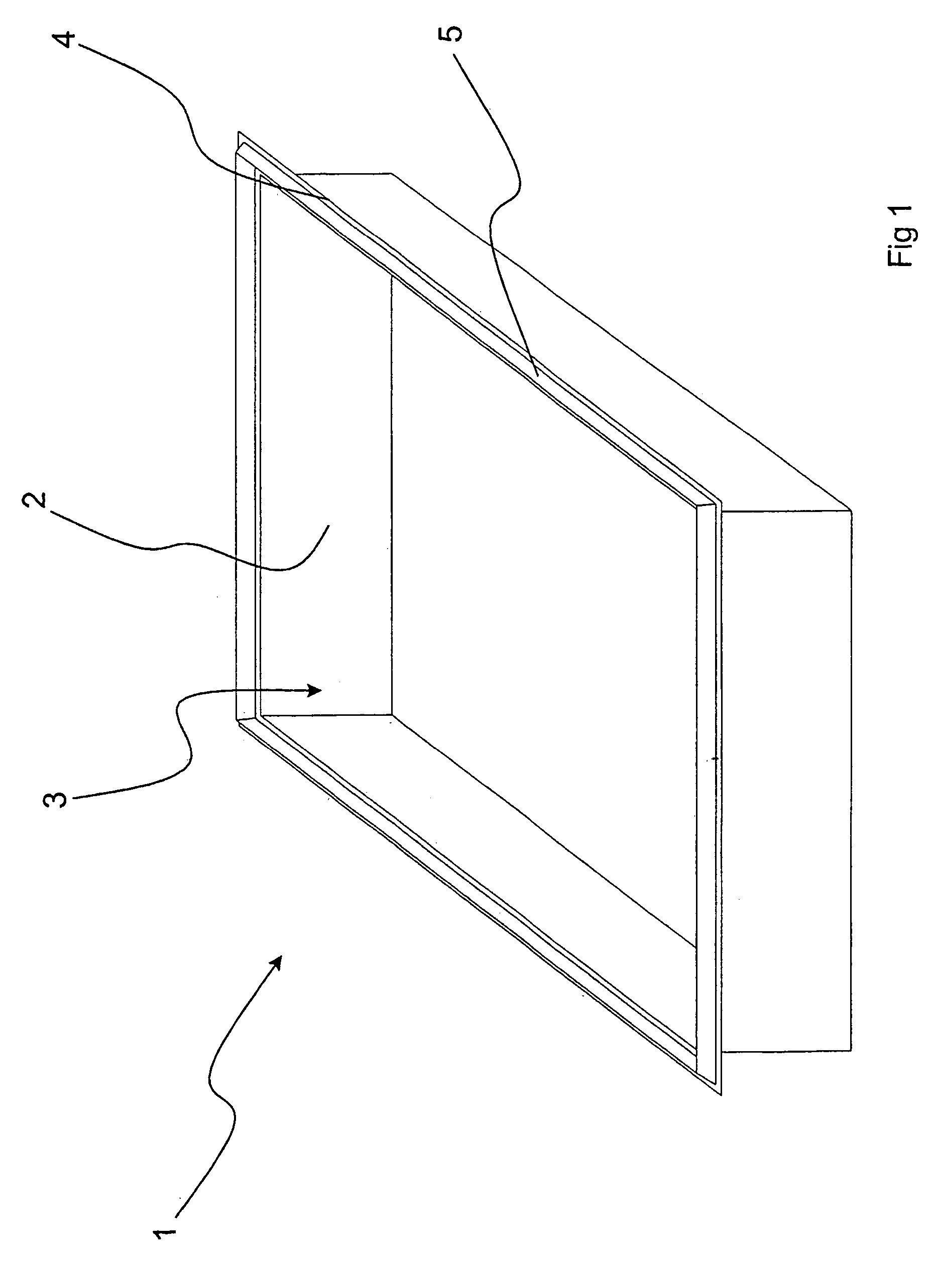
[0051]FIG. 1, to which-reference is made, illustrates an inventive device 1 for electromagnetic shielding.

[0052]The device 1 comprises a casing 2 with an opening 3 and a flange 4 surrounding the opening 3. The casing 2 has substantial electrical conductivity and can thus be made of metal or metallised plastic. The casing 2 may also comprise a body without substantial conductivity, in which case a layer of substantial conductivity is applied to the inner and / or outer surface of the casing 2.

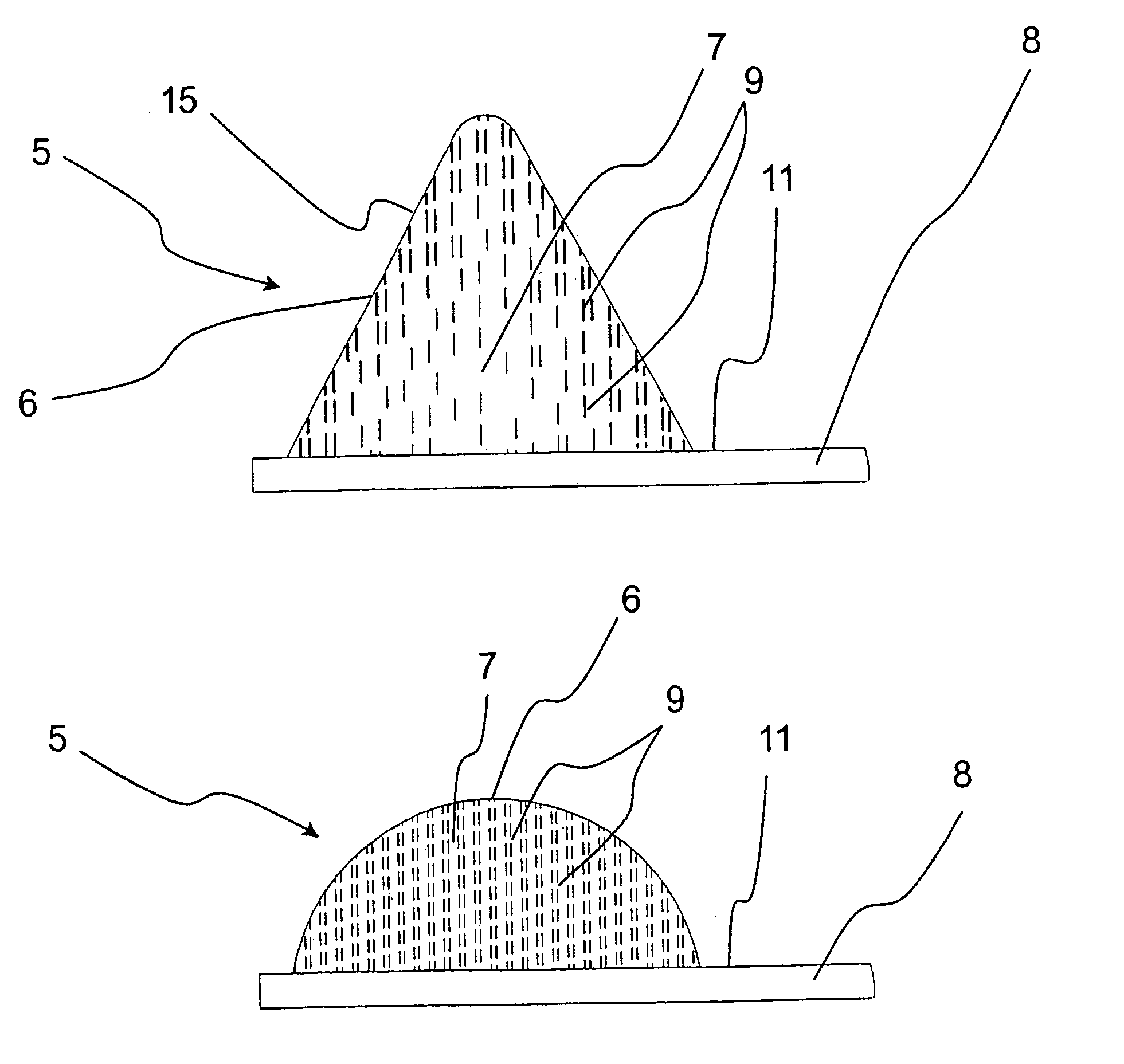
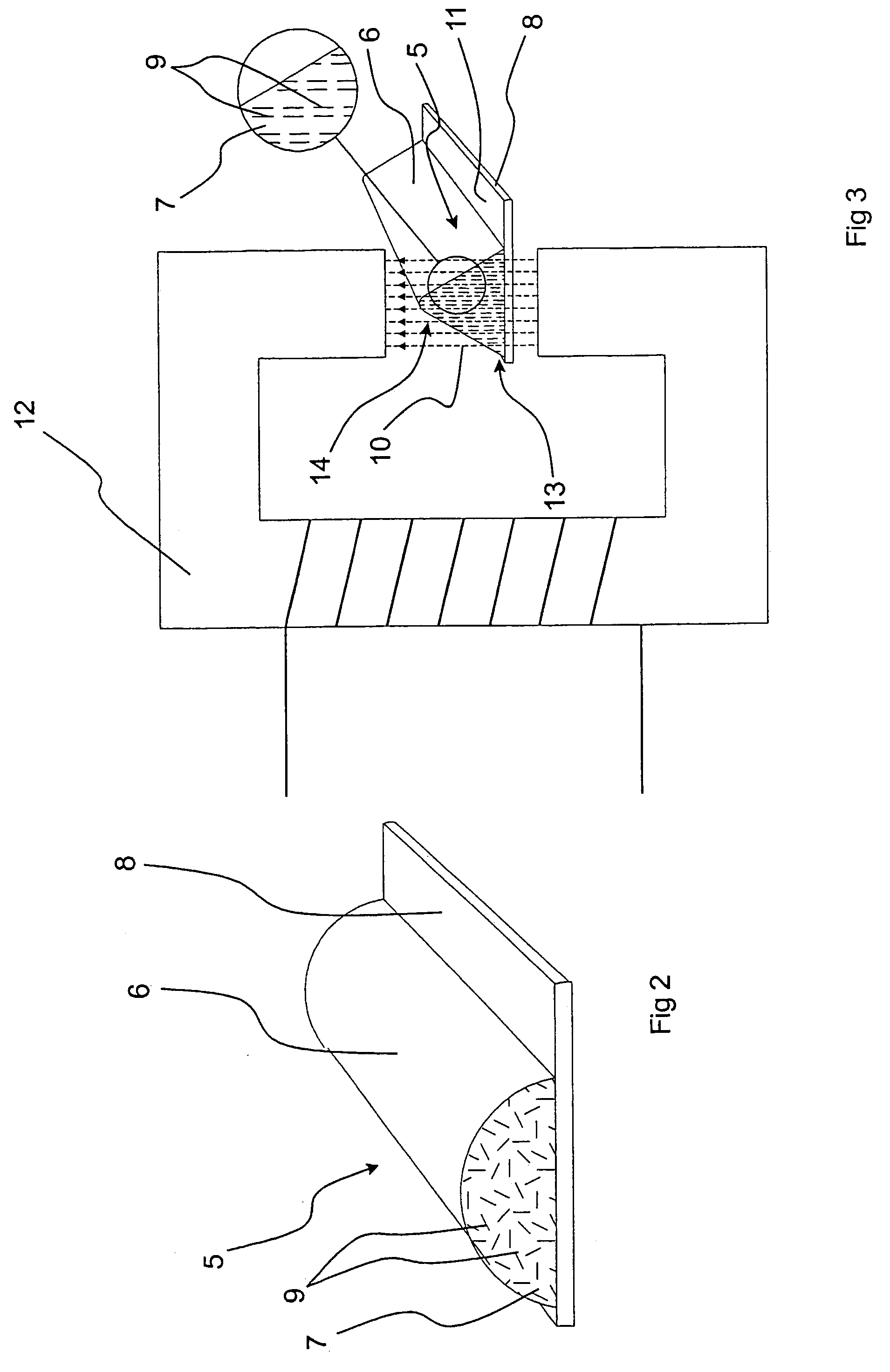
[0053]The device 1 further has an element 5, which is applied to the circumferential flange 4 and has a shape tapering from a base towards an apex. The tapering shape means that the force required for compressing the element 5, and thus providing good electric contact, is reduced.

[0054]The element 5 is made of an elastic material which carries particles with substantial electrical conductivity. According to a preferred embodiment, the elastic material consists of silicone rubber while the particle...


PUM

PropertyMeasurementUnit
magnetic fieldaaaaaaaaaa
diameteraaaaaaaaaa
heightaaaaaaaaaa

Abstract

A method for manufacturing an element for electromagnetic shielding. The method is characterized by the steps of arranging, along a curve corresponding to the extension of the completed element, a viscous material in the form of a bead, and orienting the particles in the material by applying a magnetic field across the bead. The material carries particles with substantial electrical conductivity and also ferromagnetic and / or ferrimagnetic properties. Also disclosed are a corresponding element for electromagnetic shielding, a device for electromagnetic shielding including such an element, use of such an element in a mobile phone and at a base station, and also a mobile phone and a base station including such an element.

Description

FIELD OF THE INVENTION[0001]The present invention relates to an element for electromagnetic shielding, a method for manufacturing thereof and a device comprising such an element. More specifically, the invention concerns such an element for electromagnetic shielding, comprising an elastic material which carries particles with substantial electrical conductivity.BACKGROUND ART[0002]For expedient function, electronic-equipment must, usually be shielded from electromagnetic radiation. The equipment may also comprise components which themselves generate electromagnetic radiation that must be shielded.[0003]To provide such shielding, the electronic equipment, or its components, is normally enclosed in casings with electrical conductivity, which consequently act as a Faraday cage.[0004]To allow access to the electronic equipment or its components, these casings are usually made to be opened, in which case elastic elements of the type described by way of introduction are used to ensure the...

Claims


Application Information

Patent Timeline
Patent Type & Authority Patents(United States)
IPC IPC(8): H05K9/00B29C70/62B29C70/88H01B1/22H05K1/02H05K3/28
CPCB29C70/62B29C70/882H01B1/22H05K3/284H05K9/0015B29L2031/3061Y10T29/49067H05K2201/0215H05K2201/083H05K1/0233
Inventor MATTSSON, MAGNUSJACOBSSON, MIKAEL
Owner NOLATO SILIKONTEKNIK
Why Eureka
Try Eureka