
Switching amplifier comprising a delta-sigma modulation circuit

a switching amplifier and delta-sigma technology, applied in the direction of dc amplifiers with modulator-demodulator, amplifiers with semiconductor devices/discharge tubes, instruments, etc., can solve the problem of increasing the number of switching operations performed by the switching element in the pulse amplifier b>6/b>, reducing electric power efficiency, and increasing switching losses. , to achieve the effect of improving the distortion factor and the s/n ratio of the pulse amplifier, improving the sampling frequency

Active Publication Date: 2007-01-09
SHARP KK
View PDF12 Cites 13 Cited by
  • Summary
  • Abstract
  • Description
  • Claims
  • Application Information

AI Technical Summary

Benefits of technology

[0009]An object of the present invention is to provide a switching amplifier that can obtain a desired oscillation threshold and achieve higher electric power efficiency.
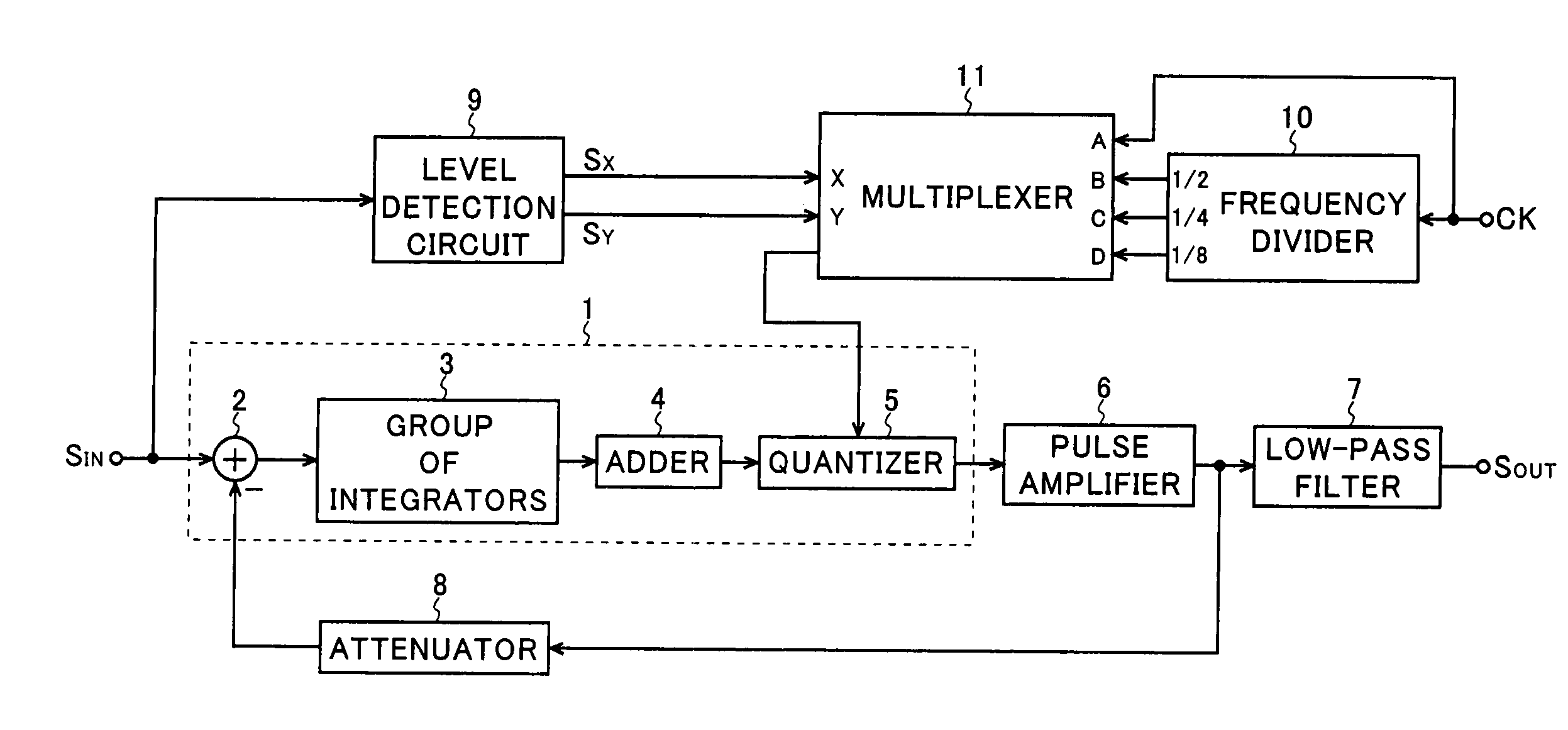
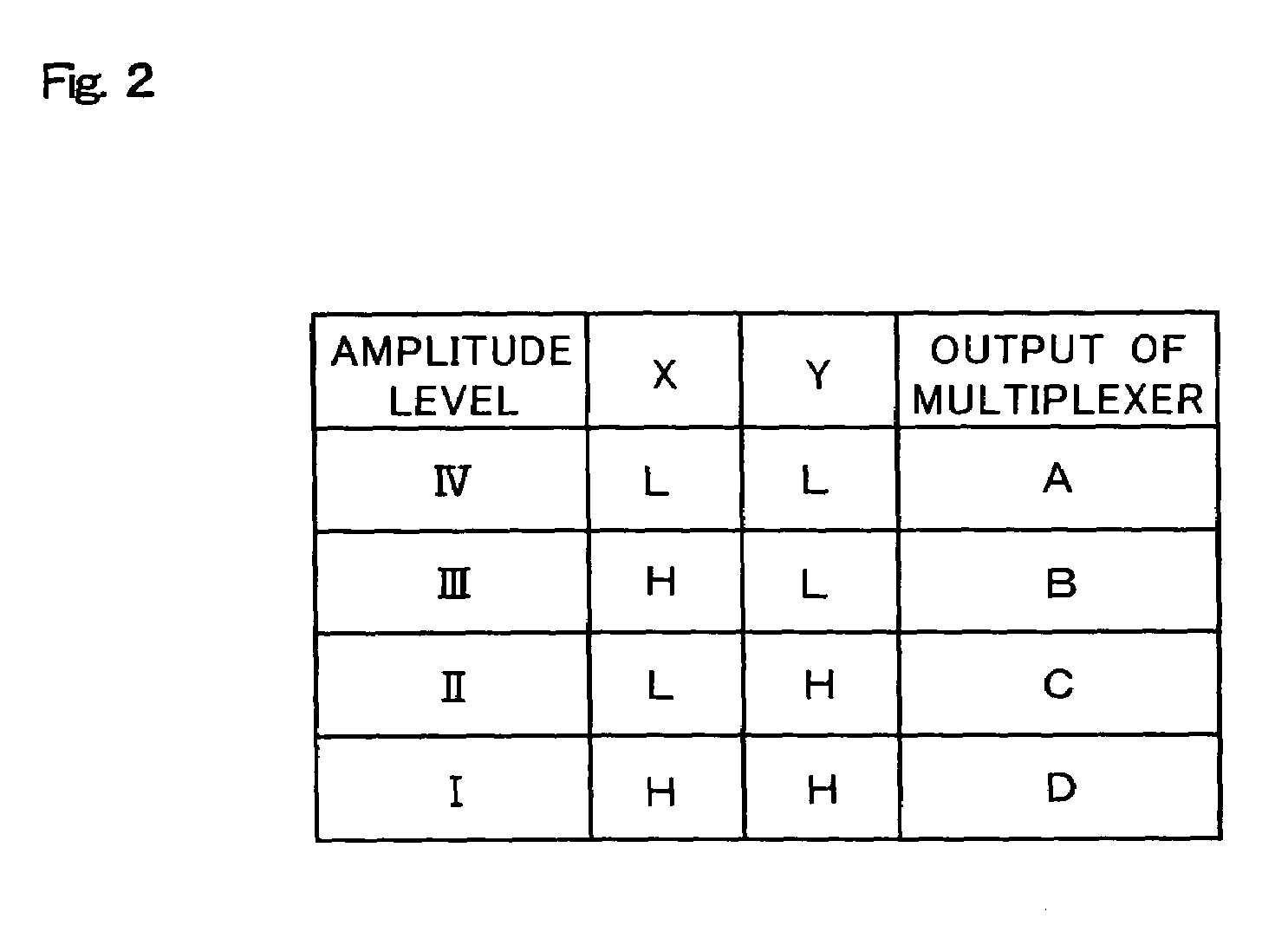
[0011]With this configuration, the sampling frequency of the delta-sigma modulation circuit varies according to the amplitude level of the input signal. This makes it possible to make higher the sampling frequency of the delta-sigma modulation circuit only when a higher oscillation threshold is required due to a high amplitude level of the input signal. This makes it possible to reduce to a minimum the number of switching operations performed by the pulse amplifier in a steady state in which the amplitude level of the input signal is low, making it possible to obtain a desired oscillation threshold and improve electric power efficiency.
[0012]Preferably, the switching amplifier configured as described above may be provided with a converter that converts an output signal of the pulse amplifier into an analog signal. This makes it possible to perform analog output.
[0013]Preferably, the switching amplifier configured as described above may be provided with an attenuator that attenuates an output signal of the pulse amplifier and then feeds back the attenuated signal to the first-stage integrator. This makes it possible to improve the distortion factor and the S / N ratio of the pulse amplifier.
[0014]Preferably, in the switching amplifier configured as described above, the plurality of integrators included in the group of integrators may be CR integrators. This makes it possible to fix the zero-point frequency of the delta-sigma modulation circuit even when the sampling frequency of the delta-sigma modulation circuit is switched from one frequency to another, and thereby stabilize the distribution of quantization noise.

Problems solved by technology

However, the problem here is that, in the conventional switching amplifier shown in FIG. 10, when the delta-sigma modulation circuit 1 is made to operate at a higher sampling frequency, the number of switching operations performed by the switching element in the pulse amplifier 6 is increased.
This increases switching losses, leading to lower electric power efficiency.
Therefore, from the viewpoint of energy saving, it is undesirable to increase unnecessarily the sampling frequency in the delta-sigma modulation circuit 1 because it results in higher electric power consumption in the switching amplifier.
Japanese Patent Application Laid-Open No. 2004-80152 discloses a delta-sigma modulator that can use a sampling frequency while switching it from one frequency to another, but does not disclose which criterion is used to switch a sampling frequency.

Method used


Image

  • Switching amplifier comprising a delta-sigma modulation circuit
  • Switching amplifier comprising a delta-sigma modulation circuit
  • Switching amplifier comprising a delta-sigma modulation circuit

Examples


Embodiment Construction

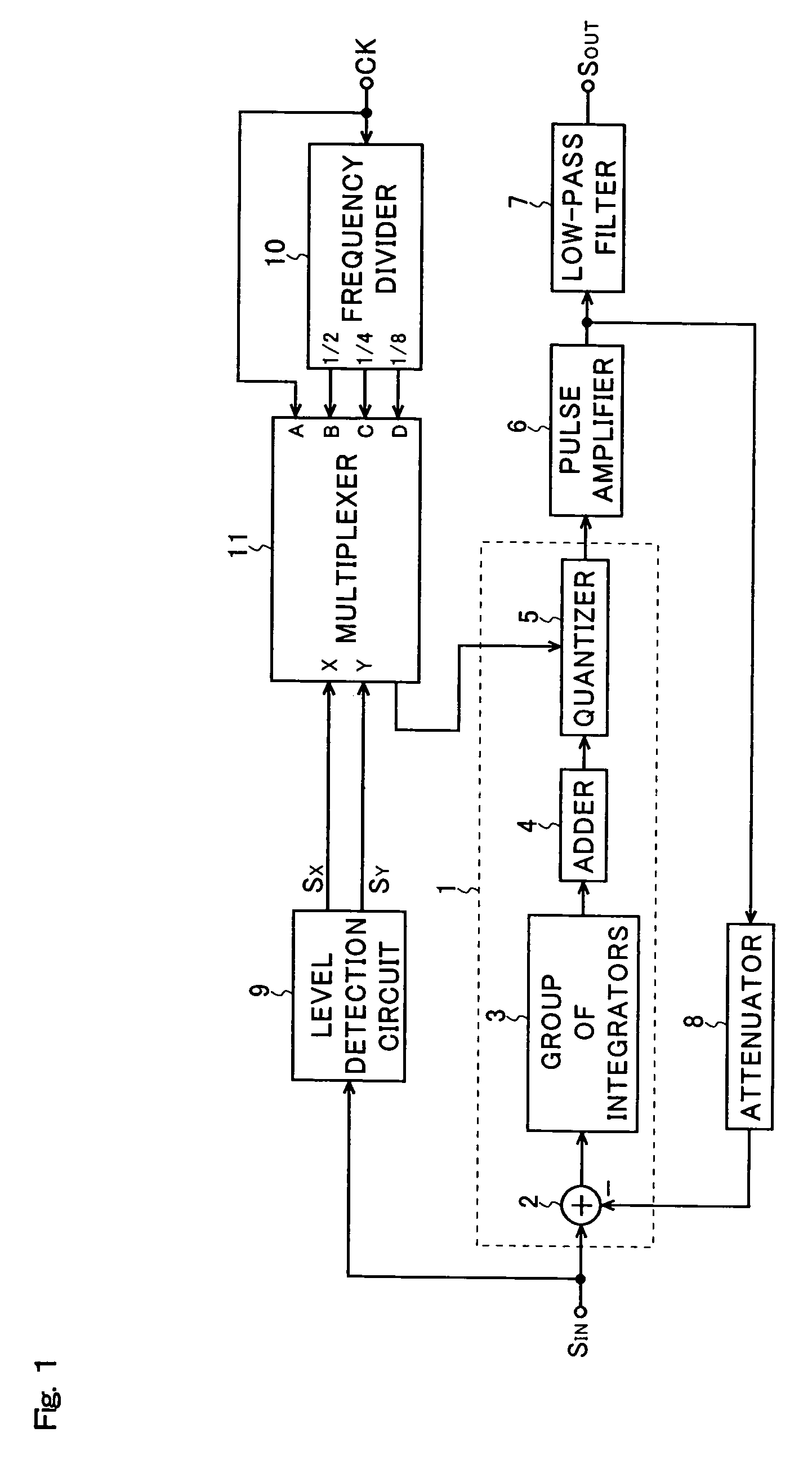
[0025]Hereinafter, embodiments of the present invention will be described with reference to the accompanying drawings. FIG. 1 shows an example of the configuration of the switching amplifier of the present invention. It is to be noted that such parts in FIG. 1 as are found also in FIG. 10 are identified with common reference numerals.

[0026]The switching amplifier of the present invention shown in FIG. 1 is a switching amplifier that performs pulse amplification by using as a switching control signal a quantized signal obtained by delta-sigma modulation. This switching amplifier is composed of a delta-sigma modulation circuit 1, a pulse amplifier 6, a low-pass filter 7, an attenuator 8, a level detection circuit 9, a frequency divider 10, and a multiplexer 11. The delta-sigma modulation circuit 1 consists of an adder 2, a group of integrators 3, an adder 4, and a quantizer 5.

[0027]The delta-sigma modulation circuit 1 converts an input signal SIN that is either an analog signal or a m...


PUM


Abstract

A switching amplifier is provided with a delta-sigma modulation circuit that performs delta-sigma modulation of an input signal that is either an analog signal or a multi-bit signal and outputs a quantized signal, a pulse amplifier that has a switching element and performs pulse amplification of the quantized signal by switching the switching element according to the quantized signal, an amplitude level detection circuit that detects the amplitude level of the input signal, and a sampling frequency adjuster that varies, according to the detection result of the amplitude level detection circuit, the sampling frequency of a quantizer included in the delta-sigma modulation circuit. The sampling frequency adjuster consists, for example, of a frequency division circuit and a multiplexer. With this configuration, it is possible to obtain a desired oscillation threshold and achieve higher electric power efficiency.

Description

[0001]This nonprovisional application claims priority under 35 U.S.C. § 119(a) on patent application No. 2004-360765 filed in Japan on Dec. 14, 2004, the entire contents of which are hereby incorporated by reference.BACKGROUND OF THE INVENTION[0002]1. Field of the Invention[0003]The present invention relates to a switching amplifier that performs pulse amplification by using as a switching control signal a quantized signal obtained by delta-sigma modulation.[0004]2. Description of Related Art[0005]An example of the configuration of a conventional switching amplifier is shown in FIG. 10. The conventional switching amplifier shown in FIG. 10 is a switching amplifier that performs pulse amplification by using as a switching control signal a quantized signal obtained by delta-sigma modulation, and is composed of a delta-sigma modulation circuit 1, a pulse amplifier 6, a low-pass filter 7, and an attenuator 8. The delta-sigma modulation circuit 1 consists of an adder 2, a group of integr...

Claims


Application Information

Patent Timeline
Patent Type & Authority Patents(United States)
IPC IPC(8): H03M1/00H03F3/38
CPCH03F3/217H03F2200/331
Inventor SUGIYAMA, MICHINORI
Owner SHARP KK
Learn More