Digital system and method for displaying images using shifted bit-weights for neutral density filtering applications

a digital system and neutral density filtering technology, applied in the field of digital display systems and methods, can solve the problems of loss of color performance, image quality and efficiency, and inability to use bits, etc., and achieve the effect of reducing the quality of the final imag

Active Publication Date: 2007-01-09
TEXAS INSTR INC
View PDF2 Cites 31 Cited by
  • Summary
  • Abstract
  • Description
  • Claims
  • Application Information

AI Technical Summary

Problems solved by technology

The time for loading the LSB bit-plane is the “peak data rate.” In conventional systems, when the LSB is less than the load-time of the DMD, then that bit cannot be used and image quality and efficiency suffers.
Another potential impact to the quality of the final image is altered or lost color performance generated by the display system.
For example, in systems employing color wheels, such as those described above, problems with the design and / or construction of the color filters on the color wheel can affect color performance.
In one specific situation, conventional filter manufacturing techniques often result in the color slope of the color filter increasing as the transmission of the filter is decreased.
In systems employing neutral density filtering (NDF), which involves increasing the PWM signal length of a color bit to a useable length beyond the load-time while decreasing the color's intensity / amplitude with lower transmissive filter segments, the decreased transmissivity of the ND filter segments typically results in such decreased color performance.

Method used


Image

  • Digital system and method for displaying images using shifted bit-weights for neutral density filtering applications
  • Digital system and method for displaying images using shifted bit-weights for neutral density filtering applications
  • Digital system and method for displaying images using shifted bit-weights for neutral density filtering applications

Examples


Embodiment Construction

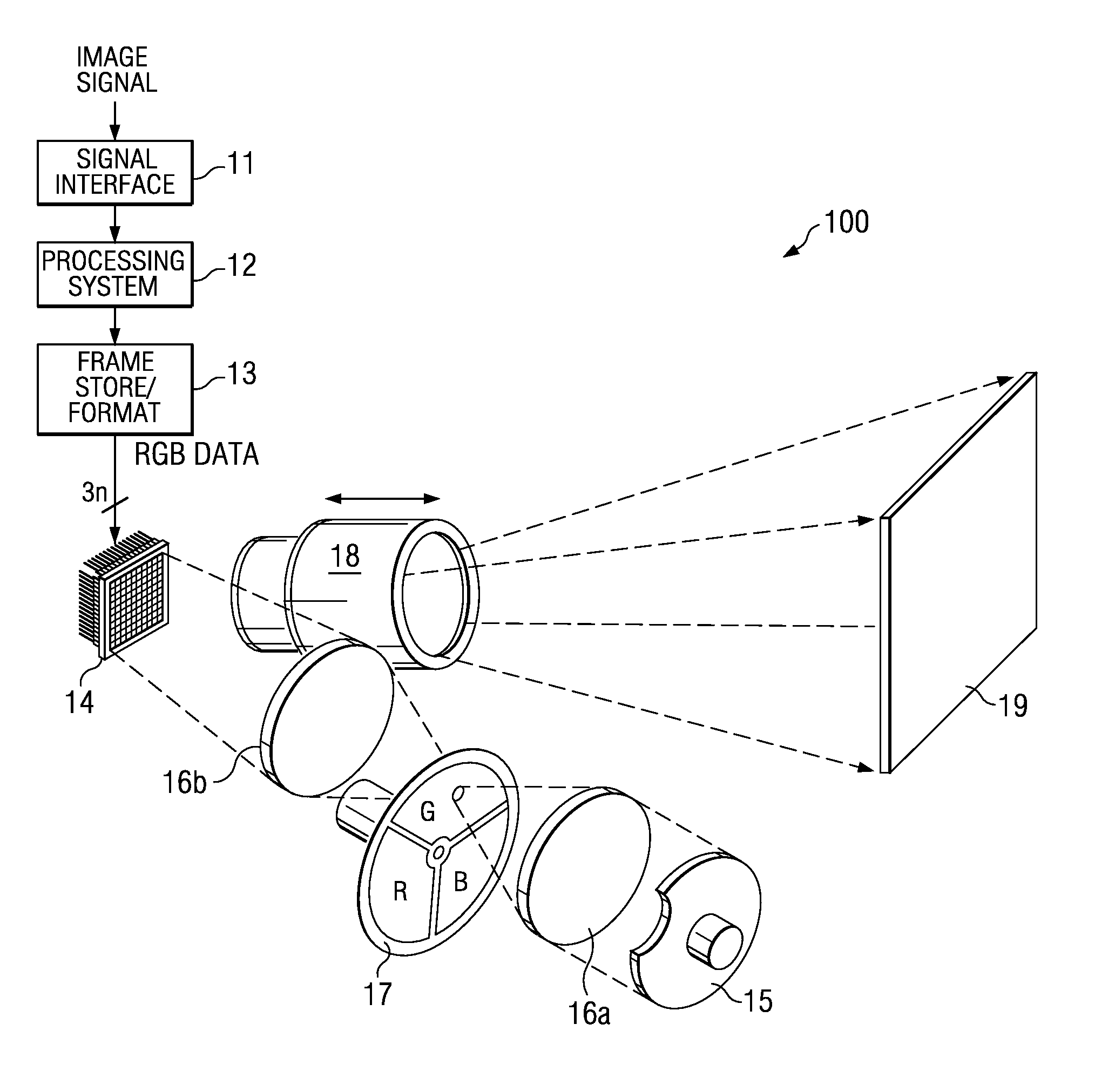
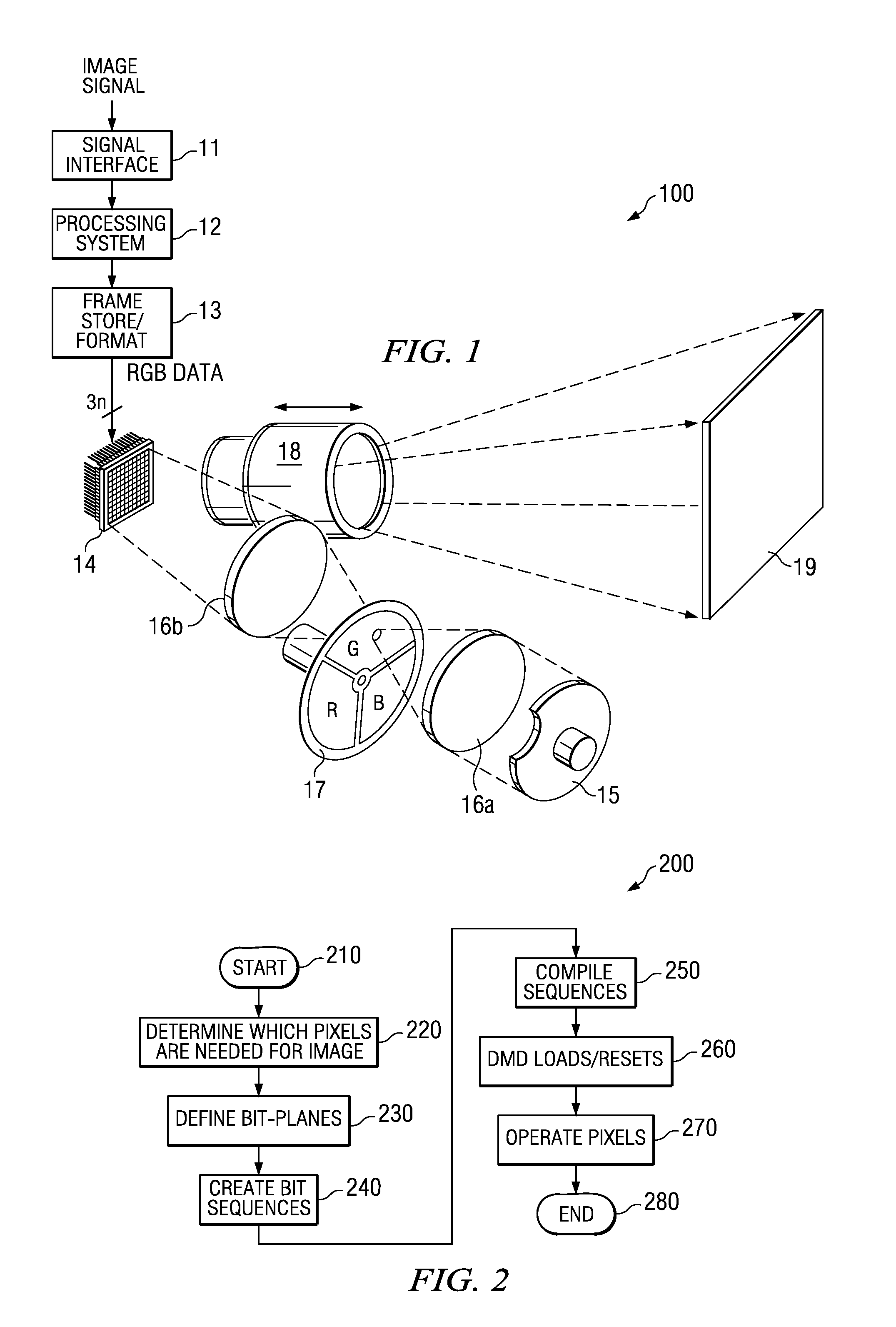
[0019]Referring initially to FIG. 1, illustrated is one embodiment of a projection visual display system 100, which uses an SLM having a DMD 14 therein to generate real-time images from an input signal. The input image signal may be from a television tuner, MPEG decoder, video disc player, video cassette player, PC graphics card, or the like. Only those components significant to main-screen pixel data processing are shown. Other components, such as might be used for processing synchronization and audio signals or secondary screen features, such as closed captioning, are not shown for simplicity.

[0020]In the illustrated embodiment, an input image signal, which may be an analog or digital signal, is input to a signal interface unit 11. In embodiments where the input signal is analog, an analog-to-digital converter (not illustrated) may be employed to convert the incoming signal to a digital data signal. Signal interface unit 11 receives the data signal and separates video, synchroniza...


PUM


Abstract

Disclosed herein are visual display systems and methods capable of having shifted bit-weights in neutral density filtering (NDF) applications. In one embodiment, a method (200) of displaying an image comprises transmitting light through an optical filter (17) comprising at least one high transmissivity portion configured to output light at an initial intensity, and at least one low transmissivity portion configured to output light at a lower intensity than the initial intensity, where the initial intensity and lower intensity output light illuminates a spatial light modulator (14). The method also includes providing a plurality of data bits (non-ND) from a predetermined number of data bits (B0–B7), where each of the plurality comprises a pulse-width longer than a load-time for operating the spatial light modulator (14). In this embodiment, the method further includes providing at least one data bit (ND) from the predetermined number of data bits, where the at least one data bit comprises an initial pulse-width less than the load-time and comprises an adjusted pulse-width greater than the load-time. Then, the method further comprises operating selected portions of the spatial light modulator (14) in coordination with the initial intensity and lower intensity output light using the pulse-widths of one or more of the plurality of data bits (non-ND) and the adjusted pulse-width of the at least one data bit (ND).

Description

TECHNICAL FIELD[0001]Disclosed embodiments herein relate generally to visual display systems and methods employing digital micro-mirror devices, and more particularly to visual display systems and methods capable of having shifted bit-weights in neutral density filtering (NDF) applications.BACKGROUND[0002]Video display systems based on spatial light modulators (SLMs) are increasingly being used as an alternative to display systems using cathode ray tubes (CRTs). SLM systems provide high-resolution displays without the bulk and power consumption of CRT systems. As used for image display applications, SLMs include arrays of micro-mirrors that reflect light to an image plane. These micro-mirrors are often referred to as picture elements or “pixels”, as distinguished from the pixels of an image. This use of terminology is typically clear from context, so long as it is understood that more than one pixel of the SLM array may be used to generate a pixel of the displayed image.[0003]Digita...

Claims


Application Information

Patent Timeline
Patent Type & Authority Patents(United States)
IPC IPC(8): G09G5/10G09G3/20G09G3/34G09G5/00
CPCG09G3/2081G09G3/34G09G3/2029G09G3/2077G09G2360/18G09G2310/0235G09G2320/0242
Inventor PETTITT, GREGORY S.BELLIS, II, HAROLD E.THOMPSON, JASON R.HEADLEY, JAMES F.SEGLER, JR., DANA F.
Owner TEXAS INSTR INC
Why Eureka
Try Eureka