Dual-edge triggered multiplexer flip-flop and method

a multiplexer and flip-flop technology, applied in the field of electronic circuits, can solve the problems of low power consumption, significant power draw, and inability to consider the complete full swing of the cmos serializer, and achieve the effect of low power drawn and high speed

Inactive Publication Date: 2007-01-09
SEIKO EPSON CORP
View PDF14 Cites 59 Cited by
  • Summary
  • Abstract
  • Description
  • Claims
  • Application Information

AI Technical Summary

Problems solved by technology

High speed flip-flops and multiplexers are used in a variety of applications, and at high frequencies, can draw significant amounts of power.
For high-frequency applications, completely full-swing CMOS serializers are not considered due to their high power consumption.
To reduce power, the high-speed blocks are designed using a differential logic family such as Current Mode Logic, but if the whole serializer is designed using a differential logic family, power consumption is still high.
The usage of two entirely different logic families, however, poses a significant signal reliability problem at the interface between the two logic families.
To alleviate this problem, careful designing is required, which requires more design resources and time.
Also, differential circuits have additional overhead of current-source reference circuits to provide reference for the tail current in the differential logic.
This approach to serializing data has significant disadvantages.

Method used


Image

  • Dual-edge triggered multiplexer flip-flop and method
  • Dual-edge triggered multiplexer flip-flop and method
  • Dual-edge triggered multiplexer flip-flop and method

Examples


Embodiment Construction

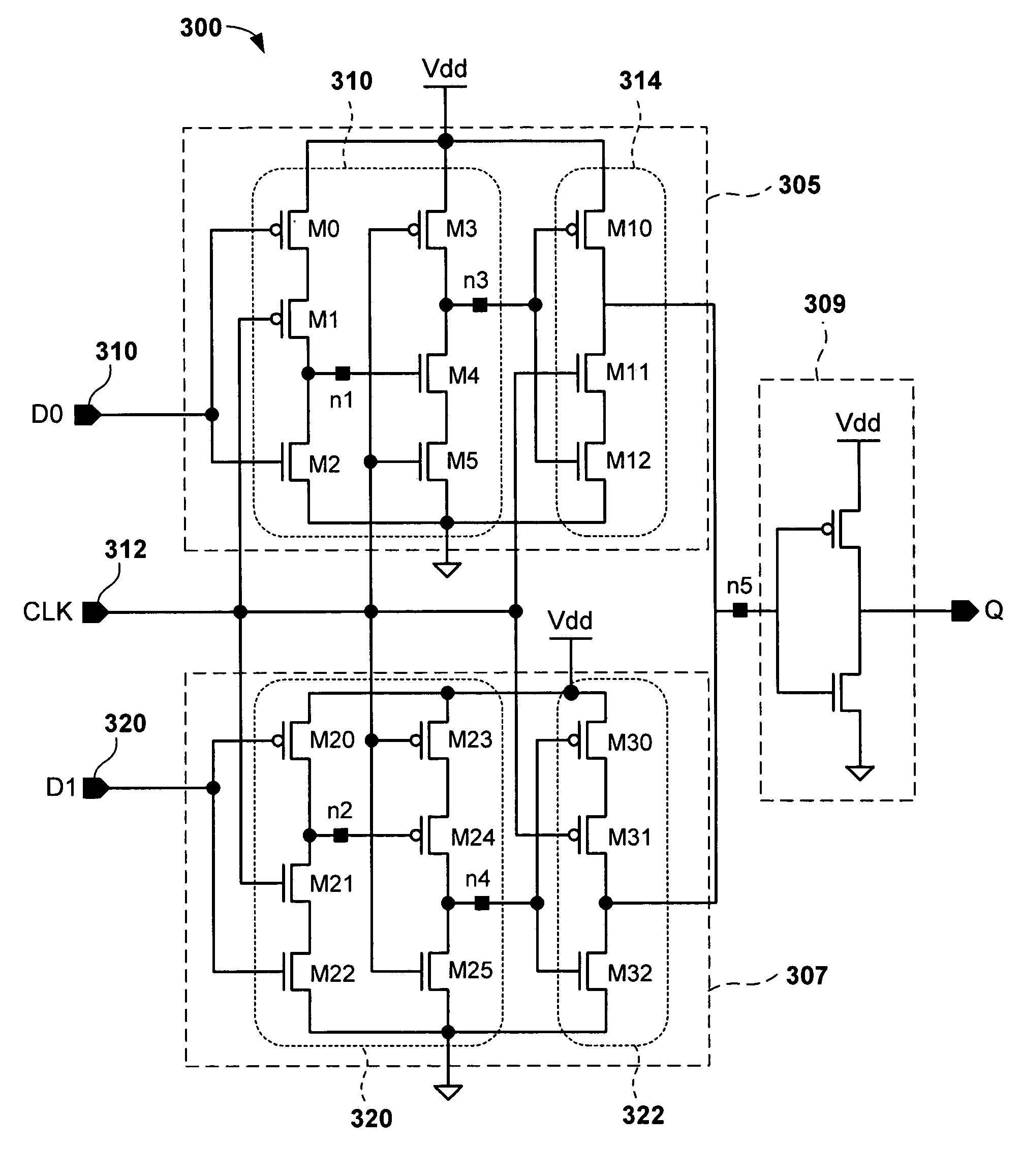
[0022]The term, “serializer” is intended to mean a device that receives parallel data from separate data streams and combines them together into a single serial data signal without any data loss. A “serializer” specifically performs this function by converting incoming parallel bits of data to a single data stream wherein the bits are provided in series.

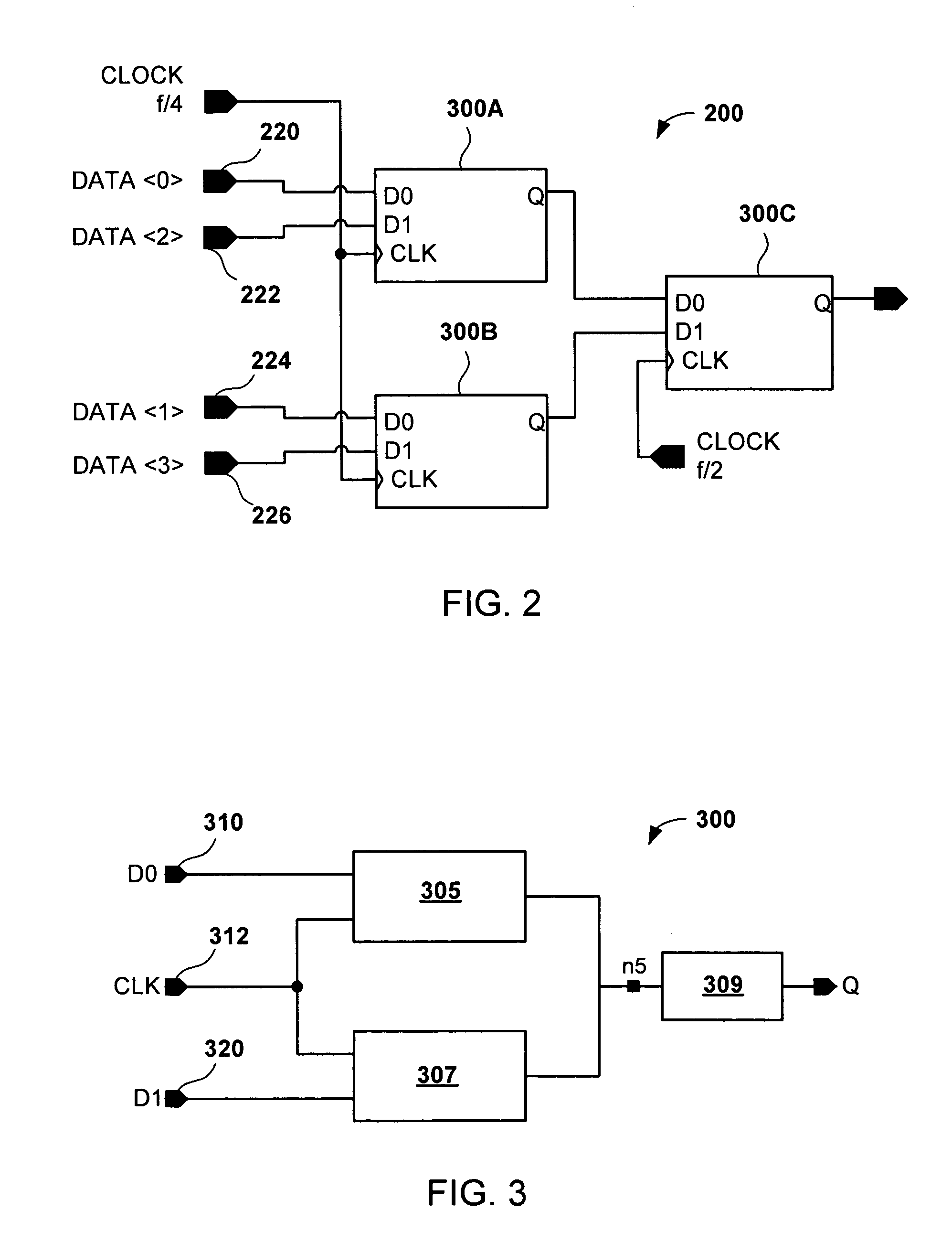
[0023]An exemplary application for a dual-edge triggered multiplexer flip-flop is shown in FIG. 2. Specifically, FIG. 2 shows an exemplary 4-to-1 serializer 200 providing an output signal Q containing data from input signals 220, 222, 224, and 226 at a frequency f. Serializer 200 is an exemplary circuit having two frequency domains f / 4 and f / 2, providing an output data signal at frequency of f. A circuit 300 is instantiated three times in the 4-to-1 serializer 200 at 300A, 300B, and 300C. Circuits 300A and 300B function in a frequency domain of f / 4 and accept data from input signals 220, 222, 224, and 126, and a clock signal coupled ...


PUM


Abstract

A dual edge multiplexing flip-flop comprises a first circuit block having a first data input, a first clock signal input, a supply voltage input, and a ground connection; a second circuit block having a second data input, a second clock signal input, a supply voltage input, and a ground connection. Each circuit block is coupled to a common output node. When a common clock signal is input into the clock signal inputs, each circuit block outputs a floating voltage during one half of each clock cycle and a voltage indicative of a corresponding data input signal during the other half of each clock cycle.

Description

CROSS-REFERENCE TO RELATED APPLICATION[0001]This application is related to commonly-assigned U.S. patent application Ser. No. 1,0990,120, filed concurrently herewith in the name of the inventor of this application, and entitled entitled, “Low-Power Serializer With Half-Rate Clocking And Method.” This related application is incorporated by reference herein in its entirety.BACKGROUND OF THE INVENTION[0002]1. Field of the Invention[0003]The present invention relates generally to an electronic circuit for serializing data from an incoming parallel data stream.[0004]2. Description of the Related Art[0005]High speed flip-flops and multiplexers are used in a variety of applications, and at high frequencies, can draw significant amounts of power. Such circuitry is used in a serializer, which is a key component in serial digital communication applications. In such systems, serializers are used to convert multi-bit low speed parallel data into high-speed serial data. For high-frequency applic...

Claims


Application Information

Patent Timeline
Patent Type & Authority Patents(United States)
IPC IPC(8): G11C7/10
CPCG11C7/1051H03M9/00G11C7/106
Inventor PADAPARAMBIL, MURALIKUMAR A.
Owner SEIKO EPSON CORP
Why Eureka
Try Eureka