
Refrigeration apparatus

a technology of refrigerating equipment and refrigeration equipment, which is applied in the field of refrigerating equipment, can solve the problems of difficulty in achieving high-efficiency and limited success of current air conditioning units having energy storage systems, and achieve the effects of lowering the temperature of the condensing unit, reducing energy consumption, and improving efficiency

Active Publication Date: 2007-01-16
GREENER ICE SPV L L C +1
View PDF57 Cites 65 Cited by
  • Summary
  • Abstract
  • Description
  • Claims
  • Application Information

AI Technical Summary

Benefits of technology

[0011]The disclosed embodiments offer the advantage of using power from electric utility companies during low demand, off-peak hours, which are usually at night, when these companies use their most efficient equipment. For example, high efficiency electric generators, typically stream-driven, produce a kilowatt-hour (KWH) for approximately 8,900 BTU. In contrast, a peak hour high capacity electrical generator, such as a gas turbine, can use as much as 14,000 BTU to produce the same KWH of electricity. Second, the transmission lines also run cooler at night resulting in higher efficiency of energy usage. Finally, for air-cooled air-conditioning systems, operating the system at night affords a higher efficiency by lowering the temperature of the condensing unit.
[0012]The disclosed refrigerant-based energy storage and cooling system has the advantage of operating at high efficiency providing an overall system that shifts power usage without significant total energy losses and with the increased efficiencies of off-peak power generation and off-peak compressor-based refrigerant cooling, a net reduction in the total energy consumption of an individual operating unit.

Problems solved by technology

Current air conditioning units having energy storage systems have had limited success due to several deficiencies including reliance on water chillers, that are practical only in large commercial buildings, and have difficulty achieving high-efficiency.

Method used


Image

  • Refrigeration apparatus
  • Refrigeration apparatus
  • Refrigeration apparatus

Examples


Embodiment Construction

[0018]While this invention is susceptible to embodiments in many different forms, there is shown in the drawings and will be described herein, in detail, specific embodiments thereof with the understanding that the present disclosure is to be considered as an exemplification of the principles of the invention and is not to be limited to the specific embodiments described.

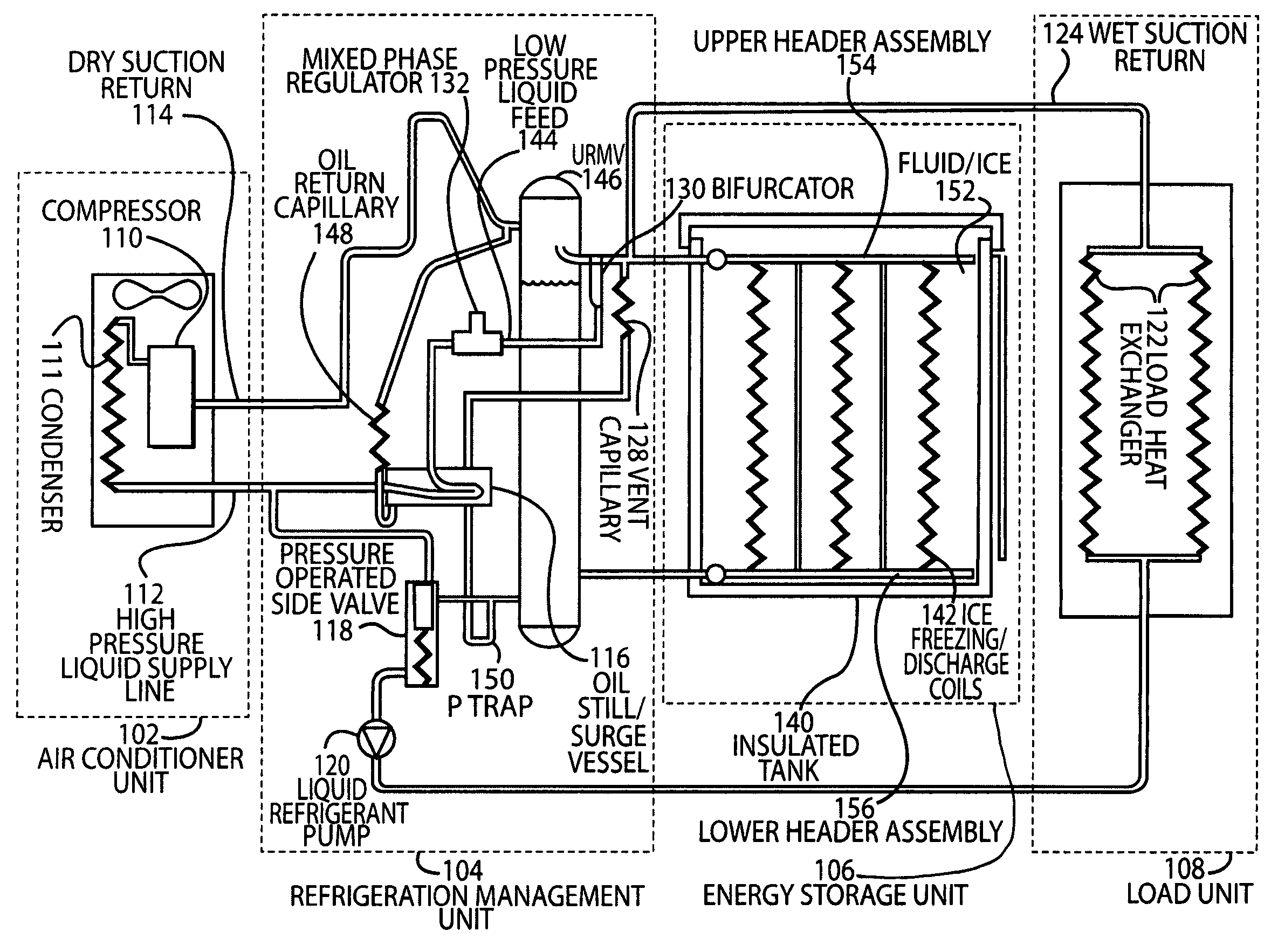
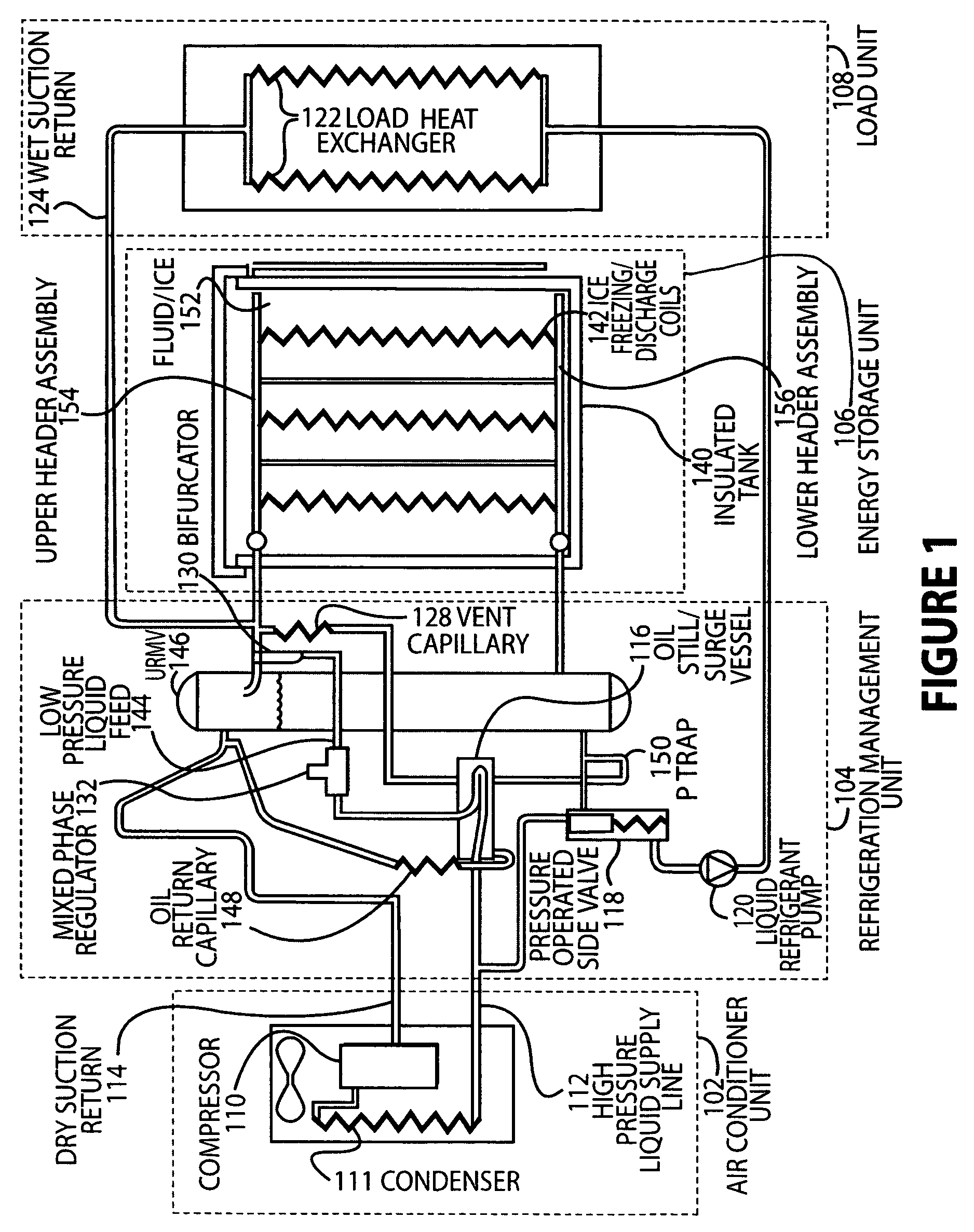
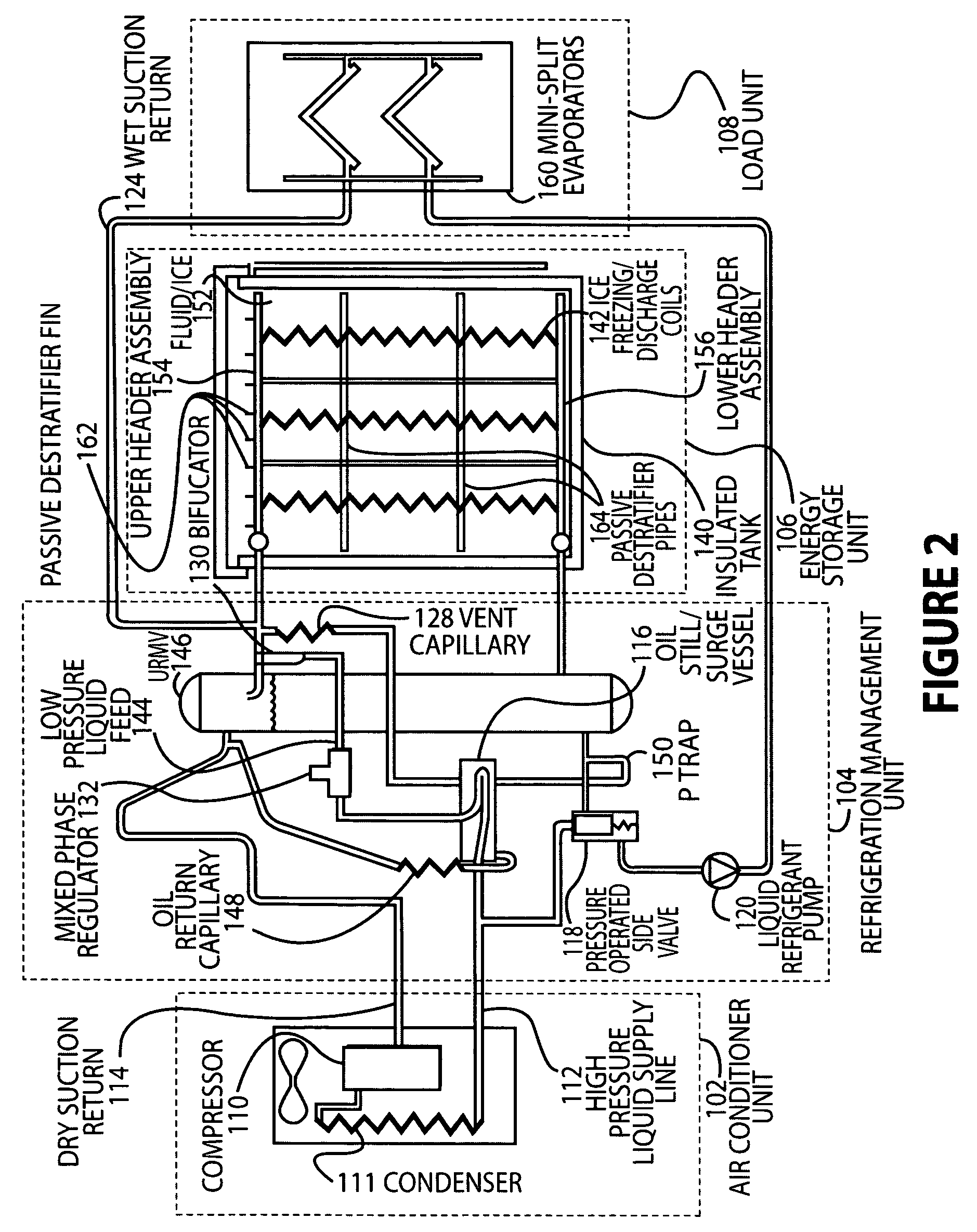
[0019]FIG. 1 illustrates an embodiment of a high efficiency refrigerant cold storage and cooling system. The described embodiments minimize additional components and use nearly no energy beyond that used by the condensing unit to store the energy. The refrigerant cold storage design has been engineered to provide flexibility so that it is practicable for a variety of applications. The embodiments can utilize stored energy to provide chilled water for large commercial applications or provide direct refrigerant air conditioning to multiple evaporators. The design incorporates multiple operating modes, the ability to a...


PUM


Abstract

Disclosed is an efficient refrigeration apparatus that provides refrigerant based energy storage and cooling. When connected to a condensing unit, the system has the ability to store energy capacity during one time period and provide cooling from the stored energy during a second time period. The system requires minimal energy to operate during either time period, and only a fraction of the energy required to operate the system during the first time period is required to operate the system during the second time period using an optional refrigerant pump.

Description

CROSS-REFERENCE TO RELATED APPLICATIONS[0001]This application is based upon and claims the benefit of U.S. provisional application No. 60 / 511,952, entitled “Refrigerant Based High Efficiency Energy Storage and Cooling System”, filed Oct. 15, 2003, the entire disclosure of which is hereby specifically incorporated by reference for all that it discloses and teaches.BACKGROUND OF THE INVENTION[0002]1. Field of the Invention[0003]The present invention relates generally to systems providing stored energy in the form of ice, and more specifically to ice storage systems used to provide cooling, especially during peak electrical demand.[0004]2. Description of the Background[0005]With the increasing demands on peak power consumption, ice storage is an environmentally benign method that has been utilized to shift air conditioning power loads to off-peak times and rates. A need exists not only for load shifting from peak to off-peak periods, but also for increases in air conditioning unit capa...

Claims


Application Information

Patent Timeline
Patent Type & Authority Patents(United States)
IPC IPC(8): F25D3/00F24F5/00F24F11/00F25D16/00
CPCF24F5/0017F24F11/006F25D16/00F24F2011/0058Y02E60/147F25B2400/23F25B2400/24F25B2400/16F24F11/30F24F2130/00F24F2130/10F24F11/62Y02E60/14F24F11/46
Inventor NARAYANAMURTHY, RAMACHANDRANKERRIGAN, ROBERT K.KAY, CHRISTOPHER A.
Owner GREENER ICE SPV L L C
Learn More