Hydropneumatic suspension system for vehicles

a technology of hydraulic suspension and vehicle, which is applied in the direction of vehicle components, transportation items, and resilient suspensions, can solve the problems that the mode of operation of the level-control system it discusses no longer meets the requirements of today's level-control systems, and is typically underloaded, and achieves good results

Active Publication Date: 2007-01-16
CARL FREUDENBERG KG
View PDF18 Cites 14 Cited by
  • Summary
  • Abstract
  • Description
  • Claims
  • Application Information

AI Technical Summary

Benefits of technology

[0011]To achieve a best possible action of the system, the opening pressure of the pressure-limiting valve and the blocking pressure of the flow-control spool valve are adjusted to one another in such a way that a predefined annular-space pressure level is achieved in the level position of the vehicle. In this context, when the suspension-cylinder stops are reached, the opening pressure of the pressure-limiting valve corresponds to the upper pressure-limiting value of the suspension system, and the blocking pressure of the flow-control spool valve corresponds to the lower pressure-limiting value of the suspensi

Problems solved by technology

However, the mode of operation of the level-control system it discusses no longer meets the requirements of today's l

Method used


Image

  • Hydropneumatic suspension system for vehicles
  • Hydropneumatic suspension system for vehicles

Examples


Embodiment Construction

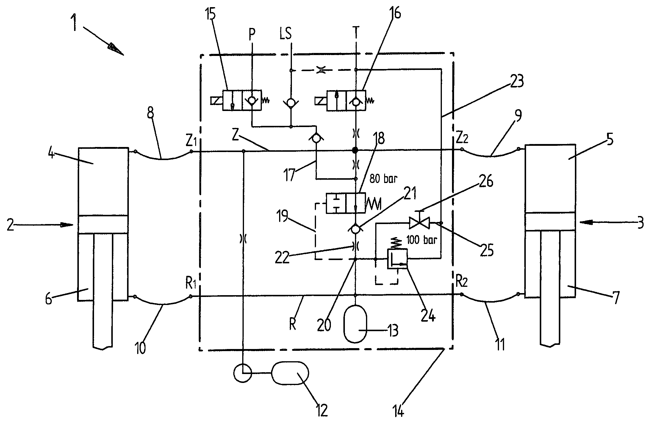
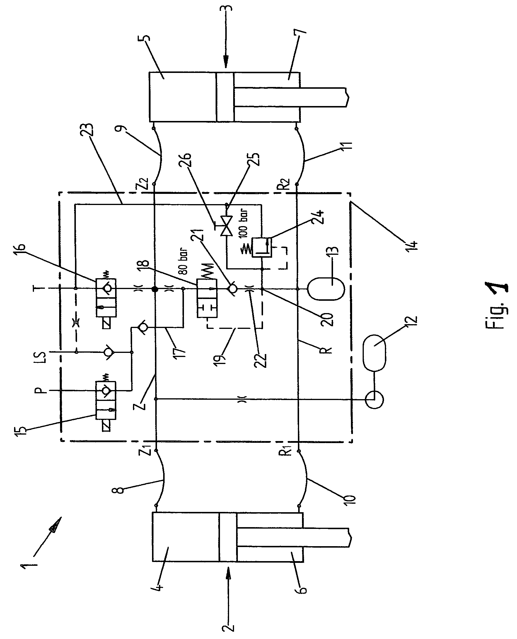
[0015]The hydropneumatic suspension system 1, shown in FIG. 1, has a simple design. Suspension cylinders 2 and 3 of suspension system 1 have cylinder chambers 4 and 5, as well as annular spaces 6 and 7, which communicate via supply lines 8, 9 and 10, 11, respectively, with the cylinder suspension circuit and the annular-space suspension circuit. Each suspension circuit Z or R is connected to a pressure accumulator 12 or 13. Dot-dash line 14 frames the control and / or regulating devices for suspension circuits Z and R. The individual parts of the level-control circuit are of a conventional design.

[0016]The vehicle-level control of suspension system 1 is carried out via 2 / 2 directional control valves 15 and 16. In the process, 2 / 2 directional control valve 15, which is actuated during the regulating-up function, is connected to pressure pump P, while 2 / 2 directional control valve 16, which assumes the regulating-down function, is connected to reservoir T. 2 / 2 directional control valves...


PUM


Abstract

A hydropneumatic suspension system for a vehicle with a level control, in particular for the front axle of a tractor, includes a first 2/2 directional control valve having a regulating-up function communicating with the pressurized oil pump and a second 2/2 directional control valve having a regulating-down function communicating with a reservoir.

Description

[0001]Priority is claimed to German Patent Application No. DE 103 06 756.6-21, filed on Feb. 17, 2003, the entire disclosure of which is incorporated by reference herein.BACKGROUND[0002]The present invention is directed to a hydropneumatic suspension system for a vehicle, in particular for the front axle of a tractor provided with a level control.[0003]Due to the high load distribution they are subjected to, tractors often require a level control system. Depending on the load acting on the axle in question, the vehicle undergoes a spring compression or rebounding, and thus a lowering or lifting of the vehicle body. These variations are sensed by a level-control system, and the vehicle body is returned to its level position by regulating the pressure levels in the hydraulic suspension cylinders of the vehicle up or down, accordingly.[0004]A very simple approach for a level-control system is described in German Patent Application DE 1 780 394 A1. However, the mode of operation of the ...

Claims


Application Information

Patent Timeline
IPC IPC(8): B60G17/00B60G9/04B60G11/26
CPCB60G11/26
Inventor BRANDENBURGER, WALTER
Owner CARL FREUDENBERG KG
Why Eureka
Try Eureka