Optical disk apparatus

Inactive Publication Date: 2007-01-16
KK TOSHIBA
View PDF14 Cites 13 Cited by
  • Summary
  • Abstract
  • Description
  • Claims
  • Application Information

AI Technical Summary

Benefits of technology

[0011]It is accordingly an embodiment of the present invention to provide an optical disk apparatus capable of generating a stable tracking error signal

Problems solved by technology

Using these optical sense signals, a tracking error signal is generated.
Use of the phase difference permits a seriously erroneous tracking error signal to be generated, if there is a flaw at the disk surface, which leads to a faulty operation,

Method used


Image

  • Optical disk apparatus
  • Optical disk apparatus
  • Optical disk apparatus

Examples


first embodiment

[0060]FIG. 8 is a block diagram showing the configuration of a tracking error signal generating circuit 85b according to a modification of the In the tracking error signal generating circuit 85b, a control signal DFCT is ANDed with a recording / unrecording signal RCD at an AND gate 107, which supplies the result to an amplifier 101. That is, when one of the signal DFCT and the signal RCD is low, the AND gate 107 outputs a low signal.

[0061]In FIG. 5, although the tracking error signal TE2 obtained by amplitude-adjusting the DPD tracking error signal VDPD is 0V in the unrecorded area, the signal TE2 might actually include noise. When the tracking error signal TE2 includes noise, it becomes unstable. Therefore, the tracking error signal TE2 is forced to be 0V in the unrecorded area. This makes the tracking error signal TE more stable.

[0062]FIG. 9 is a block diagram showing the configuration of a tracking error signal generating circuit 85c according to another modification of the first...

second embodiment

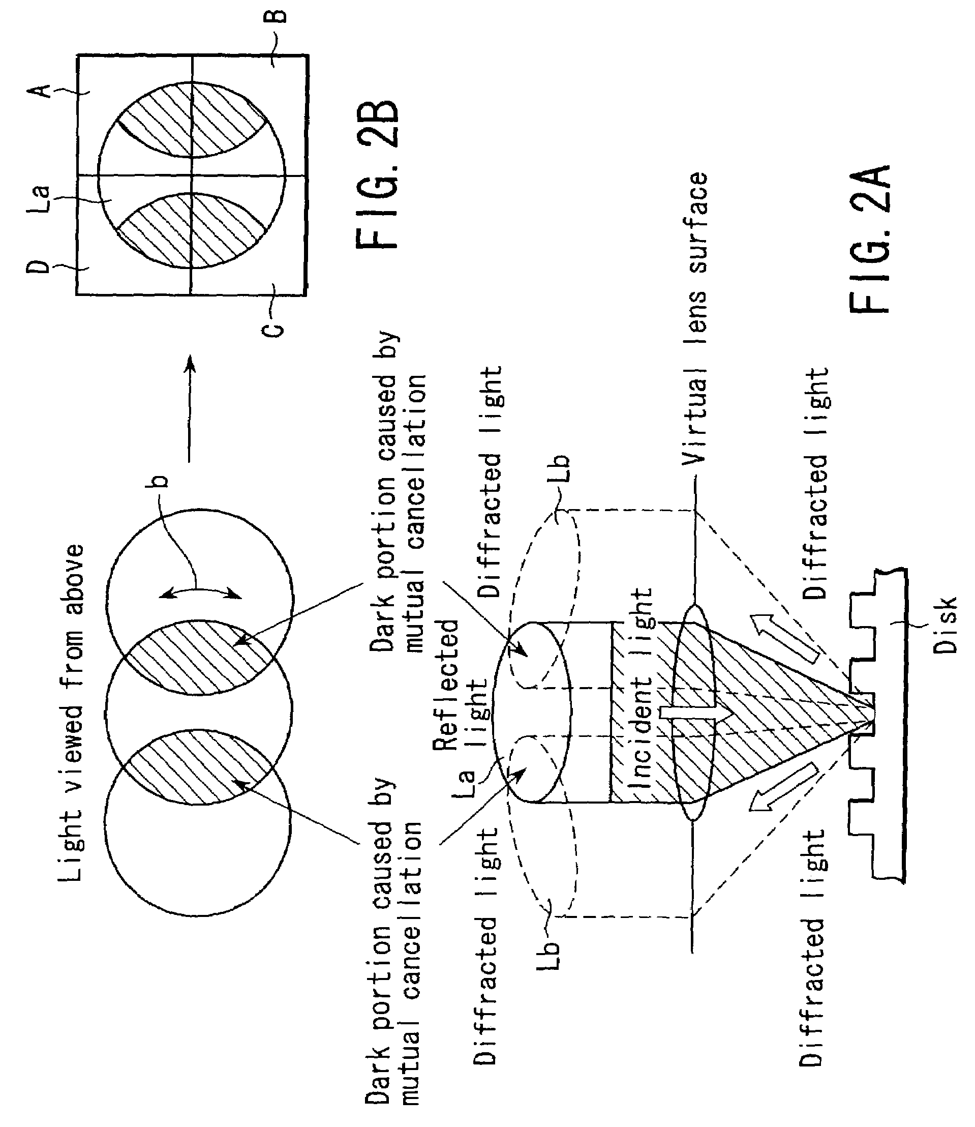
[0067]FIG. 11 is a block diagram showing the configuration of a tracking error signal generating circuit 85e according to the present invention. In the PP scheme, when the position of the object lens deviates from a desired position due to variations in the manufacture of pickups or a slight movement of the actuator, the optical axis shifts accordingly and therefore the spot on the optical sensor 84 shifts, with the result that the intensity of the light received by each detector changes. This causes an offset in the tracking error signal.

[0068]The tracking error signal generating circuit 85e uses a DPP (Differential Push Pull) scheme. As shown in FIG. 11B, on both sides of the main beam M generated from a laser diode 79, sub-beams S are generated by laser diodes 118a and 118b. The spots of the sub-beams S are projected onto adjacent tracks on both sides of the track scanned by the main beam M. Detectors F1, F2, E1, and E2 receive the sub-beams S, generate a PP signal from the sub-b...


PUM


Abstract

A Differential Phase Detecting (DPD) tracking error generating section generates a DPD tracking error signal from a plurality of sense signals supplied from an optical sensor. A Push Pull (PP) tracking error generating section generates a PP tracking error signal from a plurality of sense signals supplied from the optical sensor. The amplitude of each of the DPD tracking error signal and PP tracking error signal is adjusted suitably under the control of a CPU. The suitably adjusted signals are added by an adder, thereby generating a tracking error signal.

Description

CROSS-REFERENCE TO RELATED APPLICATIONS[0001]This application is based upon and claims the benefit of priority from the prior Japanese Patent Application No. 2002-24761, filed Jan. 31, 2002, the entire contents of which are incorporated herein by reference.BACKGROUND OF THE INVENTION[0002]1. Field of the Invention[0003]This invention relates to an optical disk recording and reproducing apparatus which projects a light beam onto a rotating optical disk and records and reproduces the information, and more particularly to the tracking servo technique for causing the light beam to trace a track on the optical disk accurately.[0004]2. Description of the Related Art[0005]In an optical disk recording and reproducing apparatus, for the light beam to trace accurately a track where pits representing information are arranged in a row, a tracking servo is indispensable which generates a tracking signal and performs position control of the pickup across the radius of the disk on the basis of the...

Claims


Application Information

Patent Timeline
IPC IPC(8): G11B7/095G11B7/09
CPCG11B7/0901G11B7/0906G11B7/0948G11B7/0943G11B7/094
Inventor NAKANE, HIROSHINAKANO, TAKESHI
Owner KK TOSHIBA
Why Eureka
Try Eureka