Optical fiber communication equipment and its applied optical systems

a technology of optical fiber communication equipment and optical systems, applied in the field of optical fiber communication modules, can solve problems such as fluctuations in laser outpu

Inactive Publication Date: 2007-01-16
ORACLE INT CORP +1
View PDF19 Cites 44 Cited by
  • Summary
  • Abstract
  • Description
  • Claims
  • Application Information

AI Technical Summary

Benefits of technology

[0059]The most typical means for changing a laser light source to a parallel plane wave is a collimator element. If the third viewpoint of the present invention is more specifically described from this standpoint, said laser light source is located at a position that is shifted from an optical axis of the collimator element, or a normal line of an incident end face for each

Problems solved by technology

As a result, laser mode competition c

Method used


Image

  • Optical fiber communication equipment and its applied optical systems
  • Optical fiber communication equipment and its applied optical systems
  • Optical fiber communication equipment and its applied optical systems

Examples


first embodiment

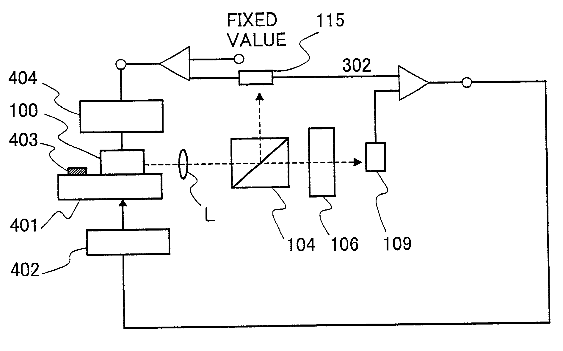
[0095]the present invention is optical-fiber communication equipment, wherein:

[0096]divergent light, which has been introduced directly or indirectly from a backward position or a forward position of a wavelength-variable laser light source or a light source where a modulator of the wavelength-variable laser light source is integrated, is changed to a parallel plane wave having flatness ten times or less as much as a wavelength by a collimator element to form a parallel light path;

[0097]a wavelength filter having at least two or more transmission peaks is located in said parallel light path;

[0098]transmitted light or reflected light of said wavelength filter is divided by a light-path dividing means;

[0099]said divided light is introduced into a plurality of light detectors;

[0100]shifted quantity of a lasing-wavelength of said laser light source is detected by a difference between photocurrents passing through each of said light detector;

[0101]a means for controlling a wavelength of ...

second embodiment

[0103]the present invention is optical-fiber communication equipment according to the present invention, wherein:

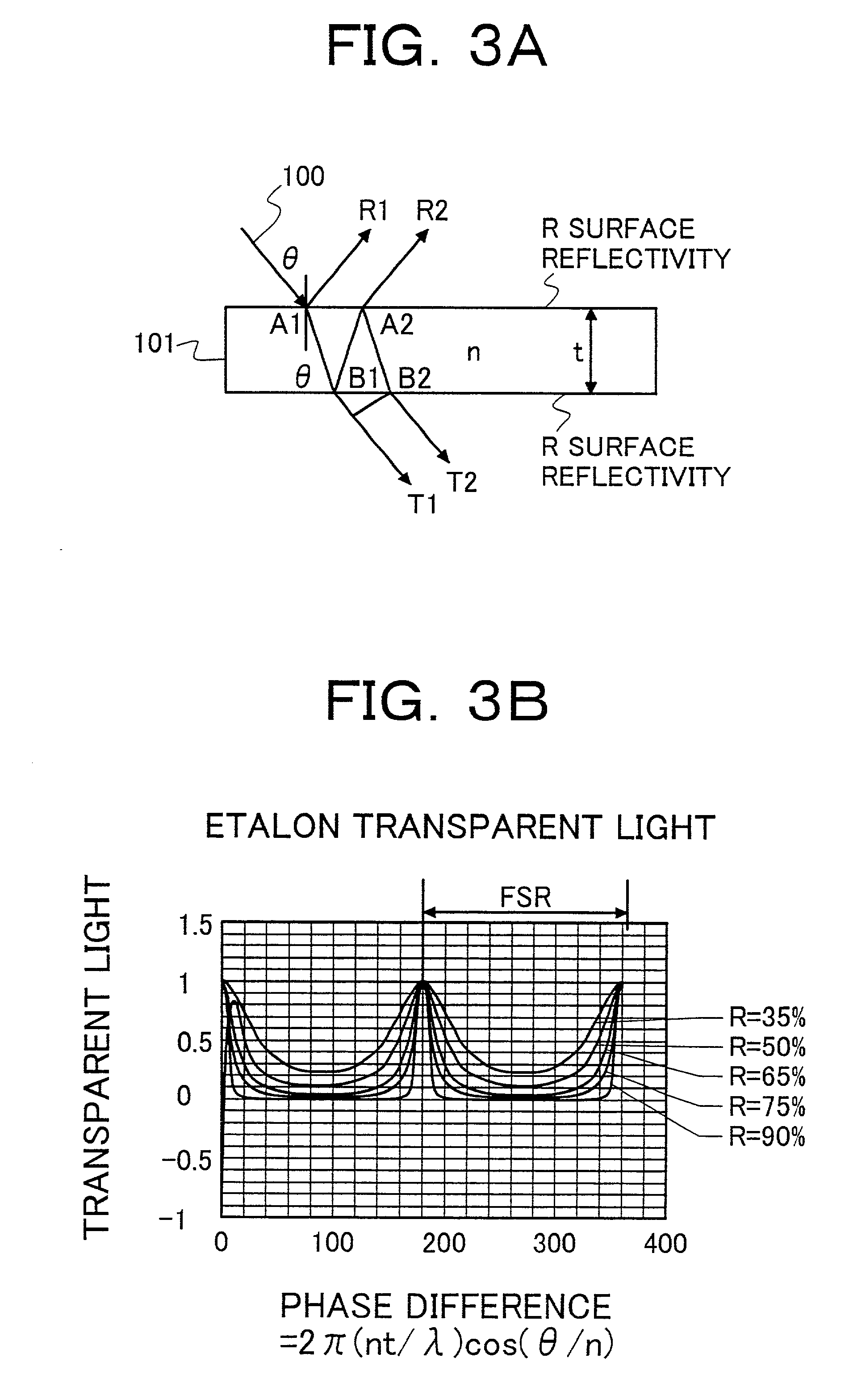
[0104]said wavelength filter is a Fabry Perot type etalon; and the light-path dividing means located in the parallel light path is an amplitude-dividing beam splitter. This is a typical example for practical use.

third embodiment

[0105]the present invention is optical-fiber communication equipment according to the present invention, wherein:

[0106]said optical-fiber communication equipment comprises a means for matching a free spectral range of the Fabry Perot etalon with a channel grid interval of Wavelength Division Multiplexing optical-fiber communication, and for changing a wavelength of the laser light source so that this wavelength is fixed to a given value of the grid.


PUM


Abstract

An object of disclosed technology is to control lasing wavelengths so that a wavelength shift does not occurs. Another object is to permit wavelengths of a light source for wavelength division multiplexing optical-fiber communication system to be variable in response to an ITU-TS grid. A means for achieving the objects is as follows: locating an etalon in a light path of diode laser light, which is a parallel plane wave changed by a collimator lens; generating a wavelength error signal from a difference between both of divided pieces of light from transmitted light or reflected light; and locking a wavelength of a diode laser device according to the wavelength error signal.

Description

BACKGROUND OF THE INVENTION[0001]The present invention relates to an optical-fiber communication module, and more specifically, to an optical-fiber communication module that is applied to a Wavelength Division Multiplexing optical-fiber communication system. Furthermore, the present invention relates to applied equipment that uses such optical-fiber communication module.[0002]Because optical-fiber communication provides us with high resistance to electromagnetic noise as well as long-distance, high-speed, and high-capacity communication, the optical-fiber communication enables us to construct a communication system that ensures high reliability. Conventionally, this system transmits light having one wavelength through one optical fiber. However, with the coming of high-capacity information-oriented society in recent years, higher transmission capacity is required. For this reason, technology of Wavelength Division Multiplexing optical-fiber communication system has been put into pra...

Claims


Application Information

Patent Timeline
IPC IPC(8): H04B10/04H01S3/10H01S3/13H04B10/12H04J14/02H01S5/00H01S5/022H01S5/068H01S5/0687H04B10/07H04B10/293H04B10/564H04B10/572
CPCH01S5/0687H01S5/005H01S5/02216H01S5/4087H01S5/06804H01S5/02248H01S5/02325
Inventor TATSUNO, KIMIOIDO, TATEMIIWAFUJI, YASUNORIKUWANO, HIDEYUKIBABA, NAOHIKO
Owner ORACLE INT CORP
Why Eureka
Try Eureka