Receiver capable of switching between digital and analog broadcasting signals

a technology of digital and analog broadcasting signals, applied in the field of receivers, can solve the problems of prior art broadcast receivers that cannot carry out appropriate switching operations, prior art broadcast receivers cannot properly determine, and agc circuits cannot carry out proper gain control

Inactive Publication Date: 2007-01-16
MITSUBISHI ELECTRIC CORP
View PDF11 Cites 13 Cited by
  • Summary
  • Abstract
  • Description
  • Claims
  • Application Information

AI Technical Summary

Benefits of technology

[0010]Therefore, the present invention offers an advantage of being able to appropriately switch between the reception of the digital broadcasting signal and the reception of the analog broadcasting signal according to electric wave reception conditions.

Problems solved by technology

As previously mentioned, digital broadcasting signals have amplitudes different from those of analog broadcasting signals, and a problem with the prior art receiver is therefore that the AGC circuit cannot carry out proper gain control because an intermediate frequency signal that contains both a digital broadcasting signal and an analog broadcasting signal is fed back to the AGC circuit.
However, in some cases, the prior art receiver cannot properly determine whether a broadcasting signal selected by the RF amplifier is an analog broadcasting signal or a digital broadcasting signal under the influence of interfering waves because the receiver is so constructed as to carry out the determination processing based on an intermediate frequency signal.
However, the prior art broadcast receiver cannot carry out an appropriate switching operation under the influence of interfering waves or the like.

Method used


Image

  • Receiver capable of switching between digital and analog broadcasting signals
  • Receiver capable of switching between digital and analog broadcasting signals
  • Receiver capable of switching between digital and analog broadcasting signals

Examples


embodiment 1

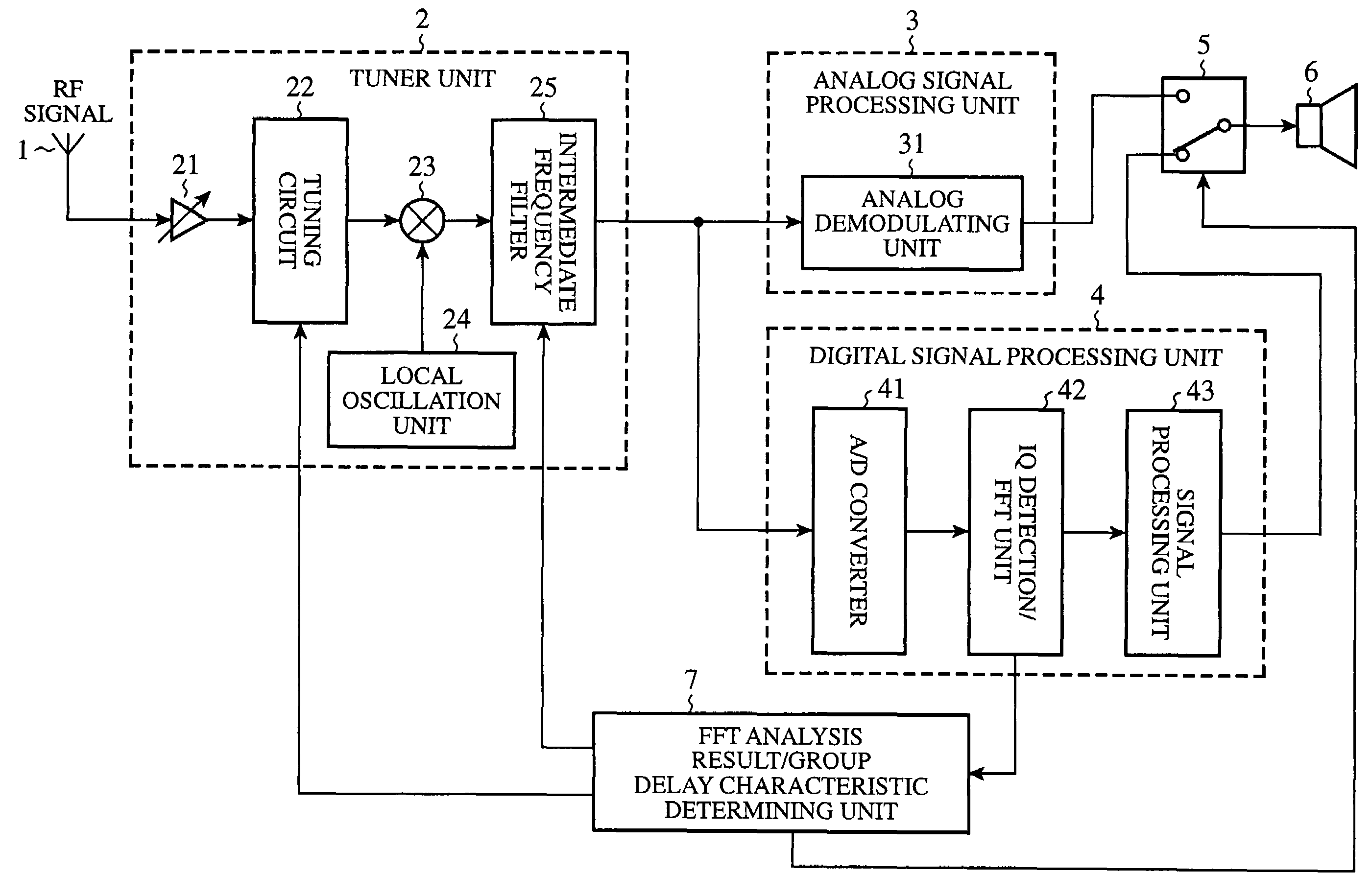
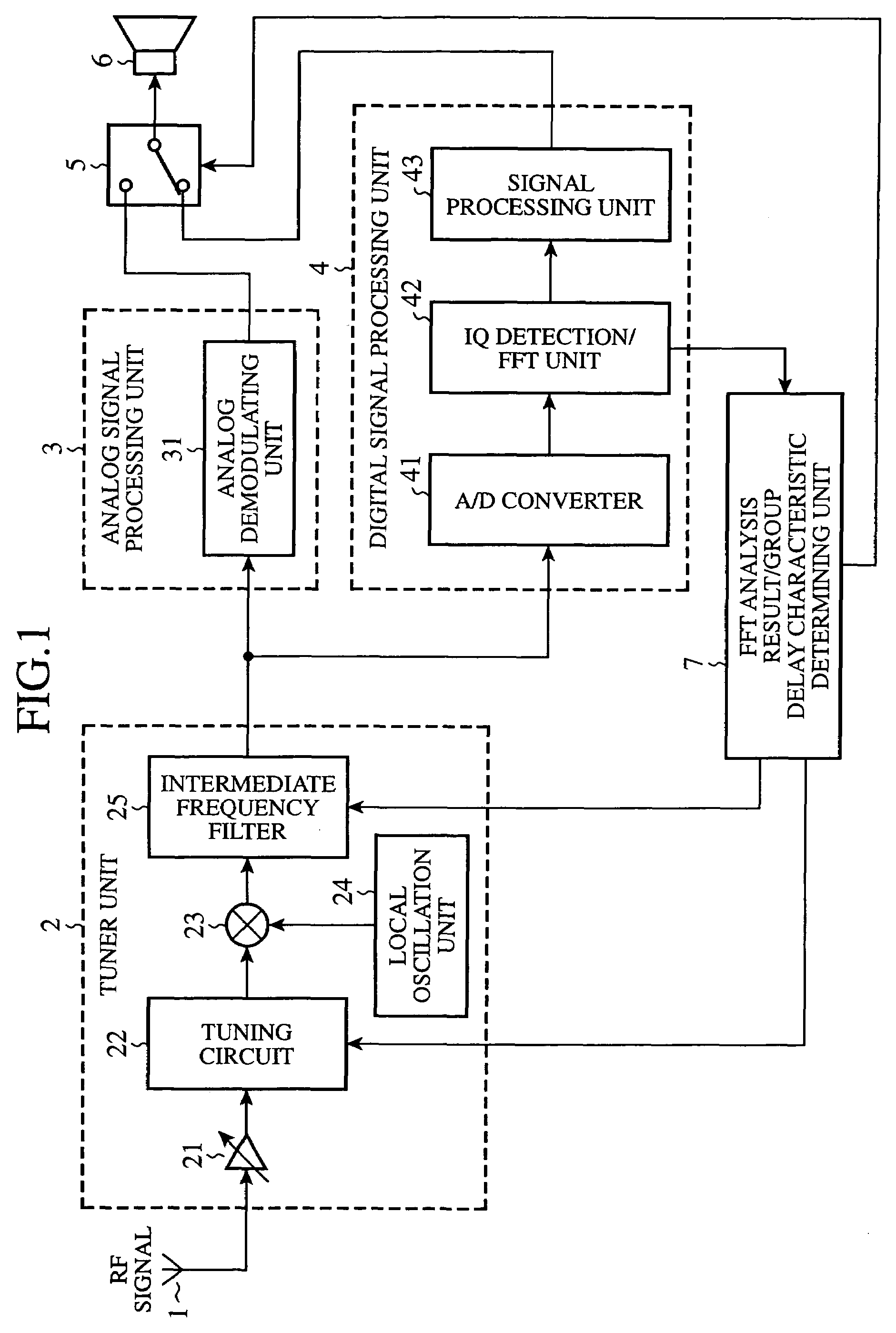
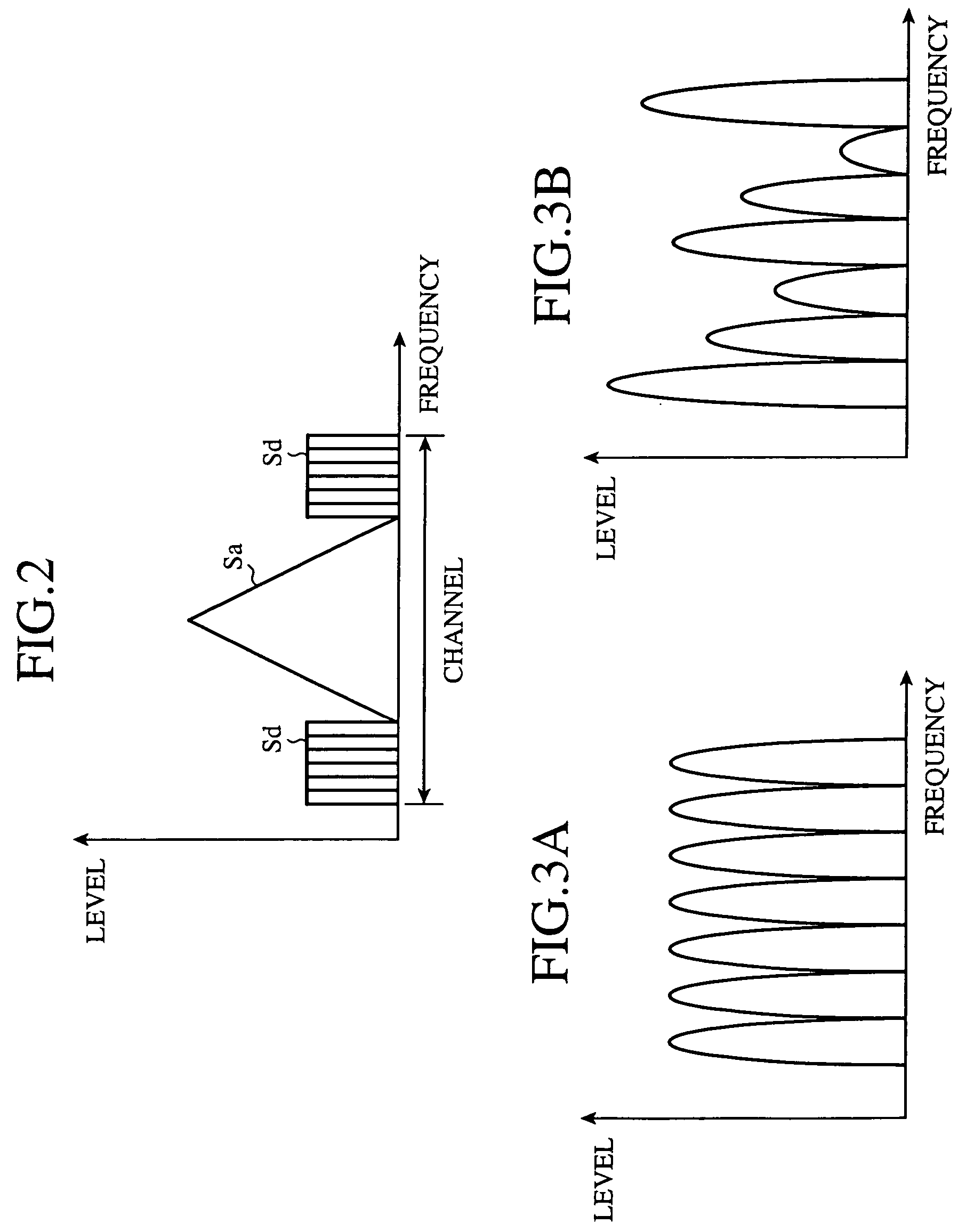
[0033]FIG. 1 is a block diagram showing the structure of a receiver in accordance with embodiment 1 of the present invention. This receiver can simultaneously receive RF signals (i.e., high frequency signals) respectively associated with a plurality of channels provided by an IBOC system that can offer both digital broadcast and analog broadcast at the same time. FIG. 2 is a diagram showing a spectrum of an RF signal (or an intermediate frequency signal) containing both an analog broadcasting signal Sa transmitted via a channel of the IBOC system and a digital broadcasting signal Sd having the same centre frequency as the analog broadcasting signal Sa and being divided into two parts arranged on both sides of the analog broadcasting signal Sa with respect to frequency (i.e., in frequency domain). In this case, the analog broadcasting signal Sa can be an FM audio signal which is frequency-modulated, and the digital broadcasting signal Sd can be an OFDM signal, i.e., a digital audio s...

embodiment 2

[0044]In embodiment 2, the details of the structures and operations of a tuning circuit 22 and an intermediate frequency filter circuit 25 of a tuner unit 2 of a receiver having the same structure as that of the embodiment 1 as shown in FIG. 1 will be explained. FIG. 6 is a circuit diagram showing the structure of a part of the receiver in accordance with embodiment 2 of the present invention. In this figure, an antenna 1, an RF amplifier 21, a mixer circuit 23 and an FFT analysis result / group delay characteristic determining unit 7, and an analog signal processing unit, a digital signal processing unit, a switching circuit, etc. not shown in the figure have the same structures as those of embodiment 1 as shown in FIG. 1, respectively.

[0045]In the tuning circuit 22, a capacitor C1, an inductance L1, and two resistors R1 and R2, one of which is selected by a switching circuit 11, are connected in parallel. Those components constitute a resonance circuit of the tuning circuit 22. The ...

embodiment 3

[0057]FIG. 11 is a circuit diagram showing the structure of a part of a receiver in accordance with embodiment 3 of the present invention. In this figure, the same components as those of embodiment 1 shown in FIG. 1 are designated by the same reference numerals, and therefore the explanation of those components will be omitted hereafter. In a tuner unit 2 of the receiver of FIG. 11, both a band stop filter circuit 26 and a switching circuit 27 for inserting the band stop filter circuit 26 between a tuning circuit 22 and a mixer circuit 23, or directly connecting the tuning circuit 22 to the mixer circuit 23 are newly added. The receiver further includes an IF level determining unit 12 (i.e., intermediate frequency signal determining means) for determining the level of an intermediate frequency signal associated with a selected channel and delivered thereto from an intermediate frequency filter circuit 25 of the tuner unit 2. The IF level determining unit 12 delivers an AGC or gain c...


PUM


Abstract

A receiver includes an FFT analysis result/group delay characteristic determining unit for determining whether or not a group of carrier signals of a digital broadcasting signal satisfies predetermined requirements, and delivers a requirement satisfaction determination signal indicating the determining result. When receiving the requirement satisfaction determination signal indicating that the group of carrier signals doesn't satisfy the predetermined requirements while the receiver is selectively receiving the digital broadcasting signal, a switching circuit switches to the reception of an analog broadcasting signal. In contrast, when receiving the requirement satisfaction determination signal indicating that the group of carrier signals satisfies the predetermined requirements while the receiver is selectively receiving the analog broadcasting signal, the switching circuit switches to the reception of the digital broadcasting signal.

Description

BACKGROUND OF THE INVENTION[0001]1. Field of the Invention[0002]The present invention relates to a receiver that can selectively receive either a digital broadcasting signal or an analog broadcasting signal.[0003]2. Description of Related Art[0004]Systems for delivering both digital broadcast and analog broadcast at the same time have been proposed. For example, in accordance with an IBOC (In Band On Channel) system proposed by iBiquity Digital Corporation in the United States, a digital broadcast signal is transmitted via a channel associated with an analog broadcast. In this case, the digital broadcasting signal is transmitted with lower power than that with which an analog broadcasting signal is transmitted so that no influence is exerted upon the analog broadcasting signal. In other words, both an analog broadcasting signal having a large amplitude and a digital broadcasting signal that consists of a number of carriers each having a small amplitude exist together in a channel (i...

Claims


Application Information

Patent Timeline
Patent Type & Authority Patents(United States)
IPC IPC(8): H04H1/00H04B1/18H04N5/46H04B1/16H04H20/00H04H20/22H04H40/18H04N5/44H04N7/06
CPCH04H20/22H04B17/20H04H40/18
Inventor NAGAHAMA, HIROYUKINAGANO, SOICHI
Owner MITSUBISHI ELECTRIC CORP
Why Eureka
Try Eureka