Viterbi decoder with direct current restoration

a decoder and direct current technology, applied in the direction of coding, code conversion, electrical equipment, etc., can solve the problems of loss of any read-back signal dc component, loss of any perpendicular recording nature, and damage to the integrity of the read-back signal, so as to avoid additional errors and eliminate the delay in the restoration of dc component

Inactive Publication Date: 2007-01-16
GUZIK TECHN ENTERPRISES
View PDF5 Cites 4 Cited by
  • Summary
  • Abstract
  • Description
  • Claims
  • Application Information

AI Technical Summary

Benefits of technology

[0010]It is an object of the present invention to provide an improved Viterbi decoder with DC component restoration based on a configuration that eliminates the delay in the restored DC component and, therefore, avoids occurrence of additional errors.
[0011]More particularly, the present invention improves the accuracy of DC component restoration by the use of the internal structure of the Viterbi decoder. For any state, bits that will appear at the Viterbi decoder output in the nearest future, if the decoder branch that corresponds to this state survives, are known. These bits are contained in the corresponding candidate register of the Viterbi decoder and in the state itself. The prediction of the future Viterbi decoder output bits are used to perform DC component restoration without delay in relation to the input signal, thus eliminating the source of bit error rate additional degradation.
[0012]The use of the Viterbi decoder with the DC component restoration according to the present invention provides for the performance improvement of data storage systems based on magnetic perpendicular recording. The main achievement is the reduction of the error rate in the data that are written to and read from the data storage system.

Problems solved by technology

The nature of perpendicular recording brings its own difficulties.
One difficulty is due to the fact that in longitudinal recording read-back signal has no DC component, while a significant part of perpendicular read-back signal power is located in low frequency region, a detrimental effect.
In conventional read channel preamplifiers, capacitance coupling is used along the signal path, resulting in loss of any read-back signal DC component.
Another difficulty with perpendicular recording is linked to interference noise from neighboring tracks.
As a consequence of the latter, a considerable amount of information in the written data is lost.
The loss of the DC component also causes baseline “wander” in a read-back signal and makes initial data recovery difficult or impossible.
This method of DC component restoration, while being somewhat effective, has however a serious drawback.
As a consequence, DC component restoration occurs with some distortions.
As a result, a source of additional errors appears that is especially noticeable when bit error rate is low.

Method used


Image

  • Viterbi decoder with direct current restoration
  • Viterbi decoder with direct current restoration
  • Viterbi decoder with direct current restoration

Examples


Embodiment Construction

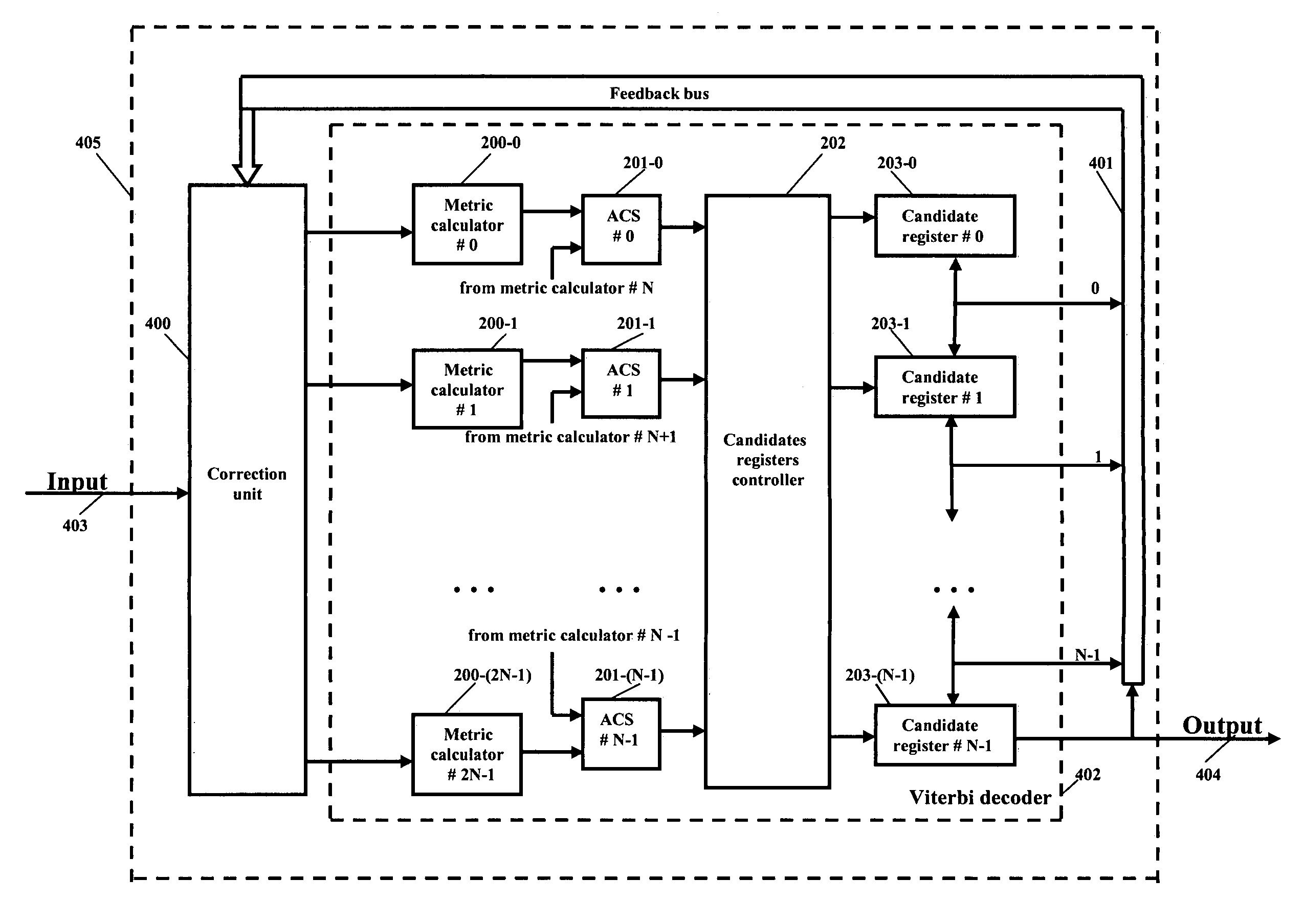
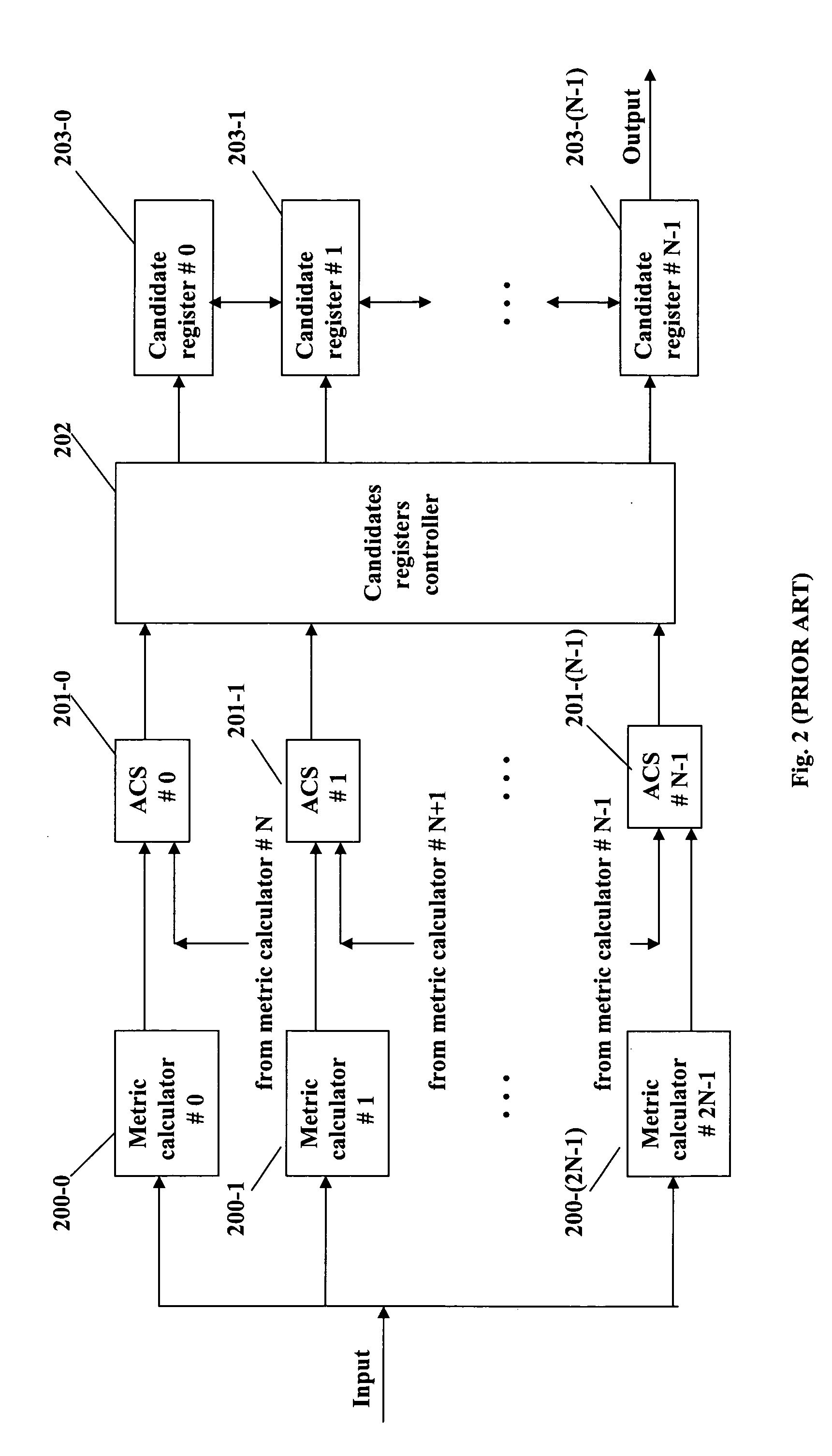
[0029]The 2N inputs of the metric calculators may be considered as partial inputs of the Viterbi decoder. In the block diagram of FIG. 2 they are united and connected to the input terminal of the decoder. The N bidirectional exchange inouts of the candidate registers may be considered as partial terminations of the decoder. According to the present invention DC component restoration is achieved by adding to a conventional-type Viterbi decoder not a single feedback circuit (as illustrated in the FIG. 3), but a set of feedback loops, one loop for each state. In every loop, a restored DC component is calculated in assumption that corresponding state will survive. The most recent sample of the restored DC component, is added to the respective current sample of the input signal and the resulting sum is placed at the corresponding partial input of the Viterbi decoder. An exemplary Viterbi decoder with DC component restoration 405 according to the present invention is shown in FIG. 4a. In ...


PUM


Abstract

A decoder for detecting data within an input signal with attenuated low frequency components that comprises a Viterbi decoder, is disclosed. Viterbi decoder internal data is used along with its output bits to reduce delay between the restored direct current (DC) component and the input signal to zero. As a result, increased accuracy of DC restoration and corresponding bit error rate reduction are achieved.

Description

FIELD OF THE INVENTION[0001]The present invention relates generally to the detection of data in channels where the signal low frequency components are suppressed or lost completely. The present invention more particularly relates to read-back signal processing in data storage systems, based on magnetic perpendicular recording and partial response maximum likelihood (PRML) detection.BACKGROUND OF THE INVENTION[0002]There is a constant demand for increasing data storage capacity in digital systems. This results in continuous development of different ways to increase the density of magnetic recording. One of the recently developed, promising architectures of data storage systems, based on magnetic recording, is perpendicular recording, which is believed to have more high density potential compared to existing longitudinal recording. In longitudinal recording the magnetic medium on a disk is magnetized in a direction parallel to the surface of the disk, whereas in perpendicular recordin...

Claims


Application Information

Patent Timeline
Patent Type & Authority Patents(United States)
IPC IPC(8): H03M13/03
CPCH03M13/6343H03M13/41
Inventor STEIN, ANATOLI B.VOLFBEYN, SEMEN P.
Owner GUZIK TECHN ENTERPRISES
Why Eureka
Try Eureka