Methods and apparatus for maintaining rotor assembly tip clearances

a technology for gas turbine engines and tip clearances, which is applied in the direction of forging/pressing/hammering apparatus, machines/engines, liquid fuel engines, etc., can solve the problems of inadvertent rubbing between the rotor blade tips and the casing, thermal expansion or contraction of the rotor and stator assemblies, and inability to achieve uniform magnitude or rate, so as to facilitate maintaining clearance and facilitate maintaining clearance.

Active Publication Date: 2007-01-23
GENERAL ELECTRIC CO
View PDF49 Cites 51 Cited by
  • Summary
  • Abstract
  • Description
  • Claims
  • Application Information

AI Technical Summary

Benefits of technology

[0005]In one aspect, a method of assembling a gas turbine engine is provided. The method comprises coupling a rotor assembly including a plurality of circumferentially-spaced rotor blades downstream from, and in flow communication with, a compressor, coupling a casing assembly circumferentially around the rotor assembly such that a clearance is defined between an inner shroud surface of the casing assembly and the rotor blade tips, and coupling a clearance control system to the casing assembly to facilitate maintaining the clearance between the casing assembly and the rotor blade tips, wherein at least a portion of an external surface of the clearance control system is formed with a textured pattern that facilitates maintaining the clearance.
[0006]In another aspect, a clearance control system for a gas turbine engine including a compressor, a fan assembly, and at least one turbine including at least one row of rotor blades is provided. The clearance control system includes an engine casing assembly that extends circumferentially around the turbine such that a clearance is defined between a tip of the turbine blades and the casing assembly, and a manifold for distributing cooling air. At least a portion of an external surface of the clearance control system includes a textured pattern that facilitates maintaining the clearance.
[0007]In a further aspect, a gas turbine engine is provided. The engine includes a compressor, a turbine downstream from and in flow communication with the compressor, an engine casing extending circumferentially around the compressor and the turbine, and a clearance control system. The turbine includes at least one row of circumferentially-spaced rotor blades. The clearance control system includes an engine casing assembly that extends circumferentially around the turbine such that a clearance is defined between a tip of the rotor blades and the casing assembly. At least a portion of an external surface of the clearance control system includes a textured pattern that extends across the external surface. The textured pattern facilitates the clearance control system maintaining the clearance.

Problems solved by technology

During engine operation, the thermal environment in the engine varies and may cause thermal expansion or contraction of the rotor and stator assemblies.
Such thermal growth or contraction may not occur uniformly in magnitude or rate.
As a result, inadvertent rubbing between the rotor blade tips and the casing may occur or the radial clearances may be more open than the design intent.
Continued rubbing between the rotor blade tips and engine casing may lead to premature failure of the rotor blade or larger clearances at other operating conditions which can result in loss of engine performance.

Method used


Image

  • Methods and apparatus for maintaining rotor assembly tip clearances
  • Methods and apparatus for maintaining rotor assembly tip clearances
  • Methods and apparatus for maintaining rotor assembly tip clearances

Examples


Embodiment Construction

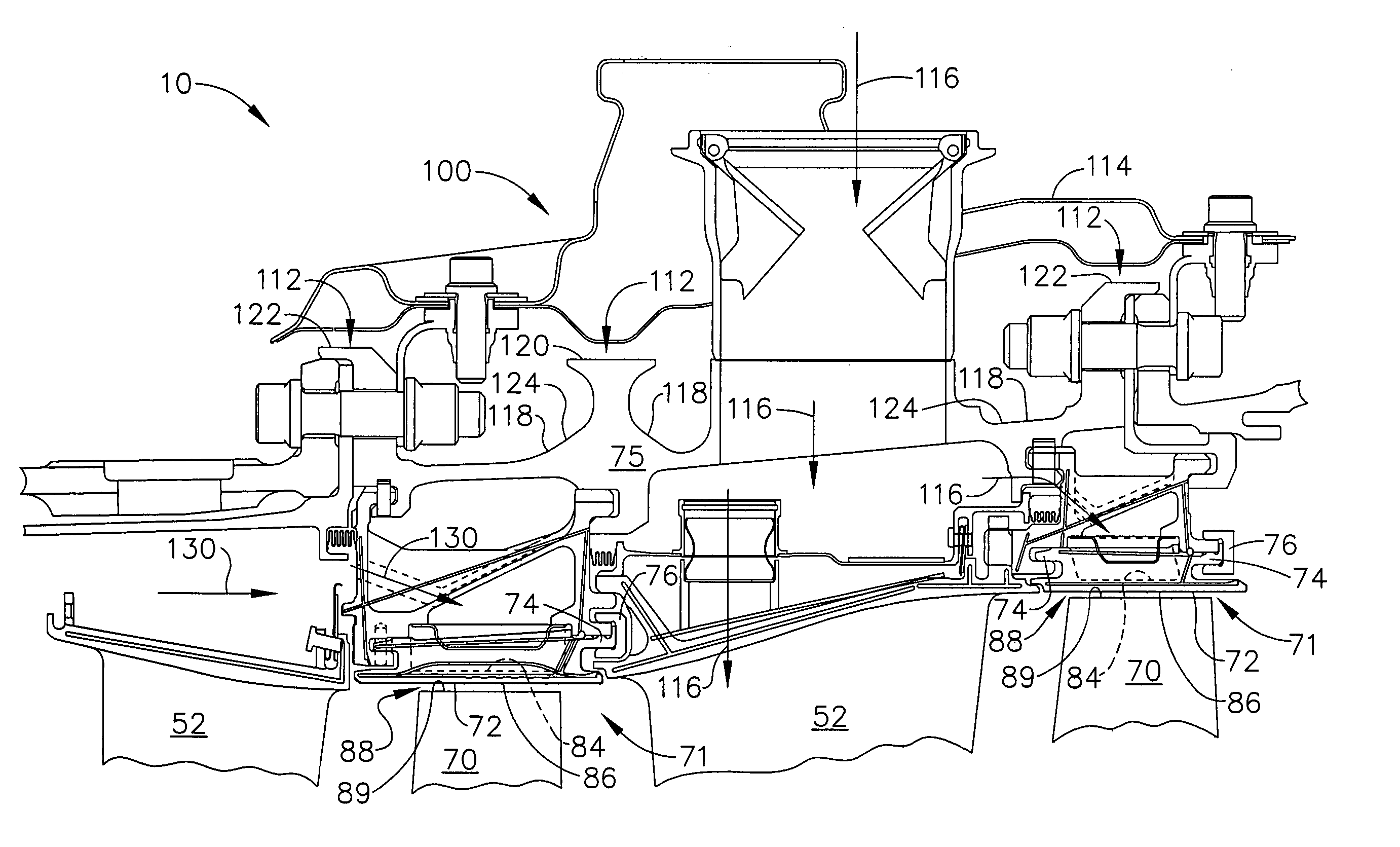
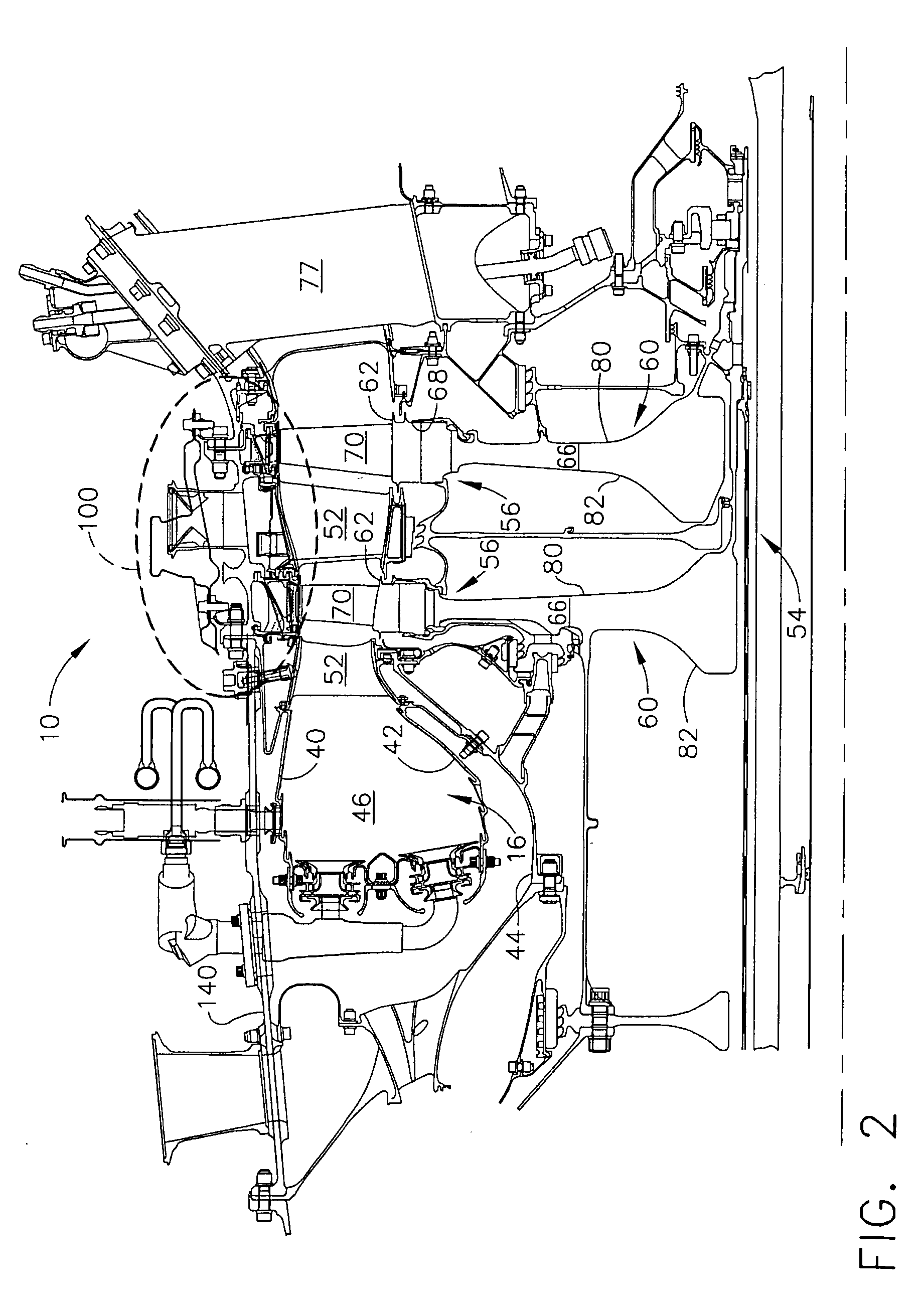
[0013]A clearance control system for a gas turbine engine that facilitates maintaining a clearance gap defined between static casing assemblies and adjacent rotating components is described below in detail. Cooling air supplied towards the static casing assemblies from the clearance control system can come from any source inside the engine according to design. For example, the cooling air may be channeled from, but is not limited to being bled from, a fan assembly, intermediate stages of a compressor, or the compressor discharge. In addition, the cooling air may also facilitate reducing disk thermal growth, which typically accounts for the majority of the total closure of blade tip clearances. Moreover, the clearance control system described in detail below facilitates tighter clearances during engine operation.

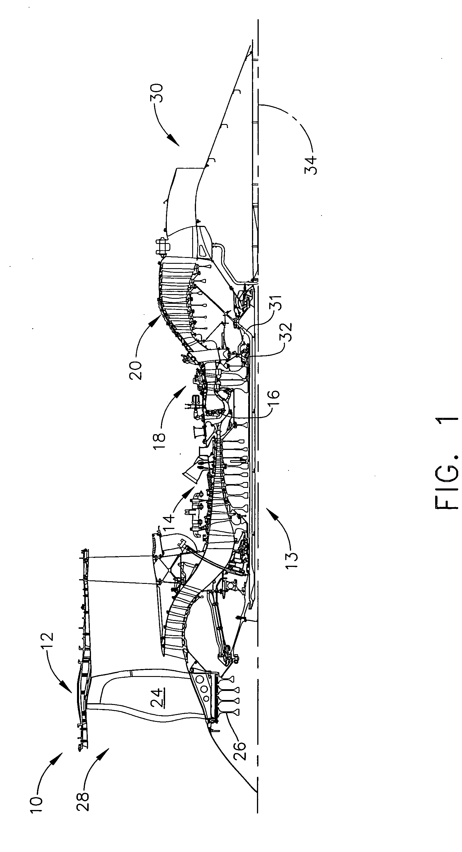
[0014]Referring to the drawings, FIG. 1 is a schematic illustration of a gas turbine engine 10 that includes, in an exemplary embodiment, a fan assembly 12 and a core engine ...


PUM

PropertyMeasurementUnit
heat transferaaaaaaaaaa
heat transfer coefficientaaaaaaaaaa
heat transfer areaaaaaaaaaaa

Abstract

A method enables a gas turbine engine to be assembled. The method comprises coupling a rotor assembly including a plurality of circumferentially-spaced rotor blades downstream from, and in flow communication with, a compressor, coupling a casing assembly circumferentially around the rotor assembly such that a clearance is defined between an inner shroud surface of the casing assembly and the rotor blade tips, and coupling a clearance control system to the casing assembly to facilitate maintaining the clearance between the casing assembly and the rotor blade tips, wherein at least a portion of an external surface of the clearance control system is formed with a textured pattern that facilitates increasing the clearance control closure capability during engine operation.

Description

BACKGROUND OF THE INVENTION[0001]This invention relates generally to gas turbine engines, and more particularly, to methods and apparatus to control gas turbine engine rotor assembly tip clearances during rotor assembly operation.[0002]Gas turbine engines typically include an engine casing that extends circumferentially around a compressor, and a turbine including a rotor assembly and a stator assembly. The rotor assembly includes at least one row of rotating blades that extend radially outward from a blade root to a blade tip. A radial tip clearance is defined between the rotating blade tips and a shroud attached to the engine casing.[0003]During engine operation, the thermal environment in the engine varies and may cause thermal expansion or contraction of the rotor and stator assemblies. Such thermal growth or contraction may not occur uniformly in magnitude or rate. As a result, inadvertent rubbing between the rotor blade tips and the casing may occur or the radial clearances ma...

Claims


Application Information

Patent Timeline
Patent Type & Authority Patents(United States)
IPC IPC(8): F01D11/08F03B11/02
CPCF01D11/14F05D2250/18Y10T29/49323F05D2260/22141F05D2260/2214F05D2260/2212
Inventor DONG, ZHIFENGEPSTEIN, MICHAEL J.ROYAL, GLEN WILLIAMALBERS, ROBERT J.
Owner GENERAL ELECTRIC CO
Why Eureka
Try Eureka