Compact steam reformer

Inactive Publication Date: 2007-01-23
WS REFORMER
View PDF10 Cites 27 Cited by
  • Summary
  • Abstract
  • Description
  • Claims
  • Application Information

AI Technical Summary

Benefits of technology

[0019]The combustion chamber can be arranged for flameless oxidation. To that end, small-area eddies and circulations that could serve to develop and maintain flames are avoided. Low-NOx and low-wear operation thus results. Furthermore, fluctuations in the calorific value of the combustion gas are not critical.
[0020]In a preferred embodiment, one or more reaction vessels and one or more burners are disposed concentrically to one another. For instance, one centrally disposed burner is surrounded by a plurality of reaction ve

Problems solved by technology

On the contrary, upon a sudden change in load, the thermal inertia of the reaction vessel

Method used


Image

  • Compact steam reformer
  • Compact steam reformer
  • Compact steam reformer

Examples


Example

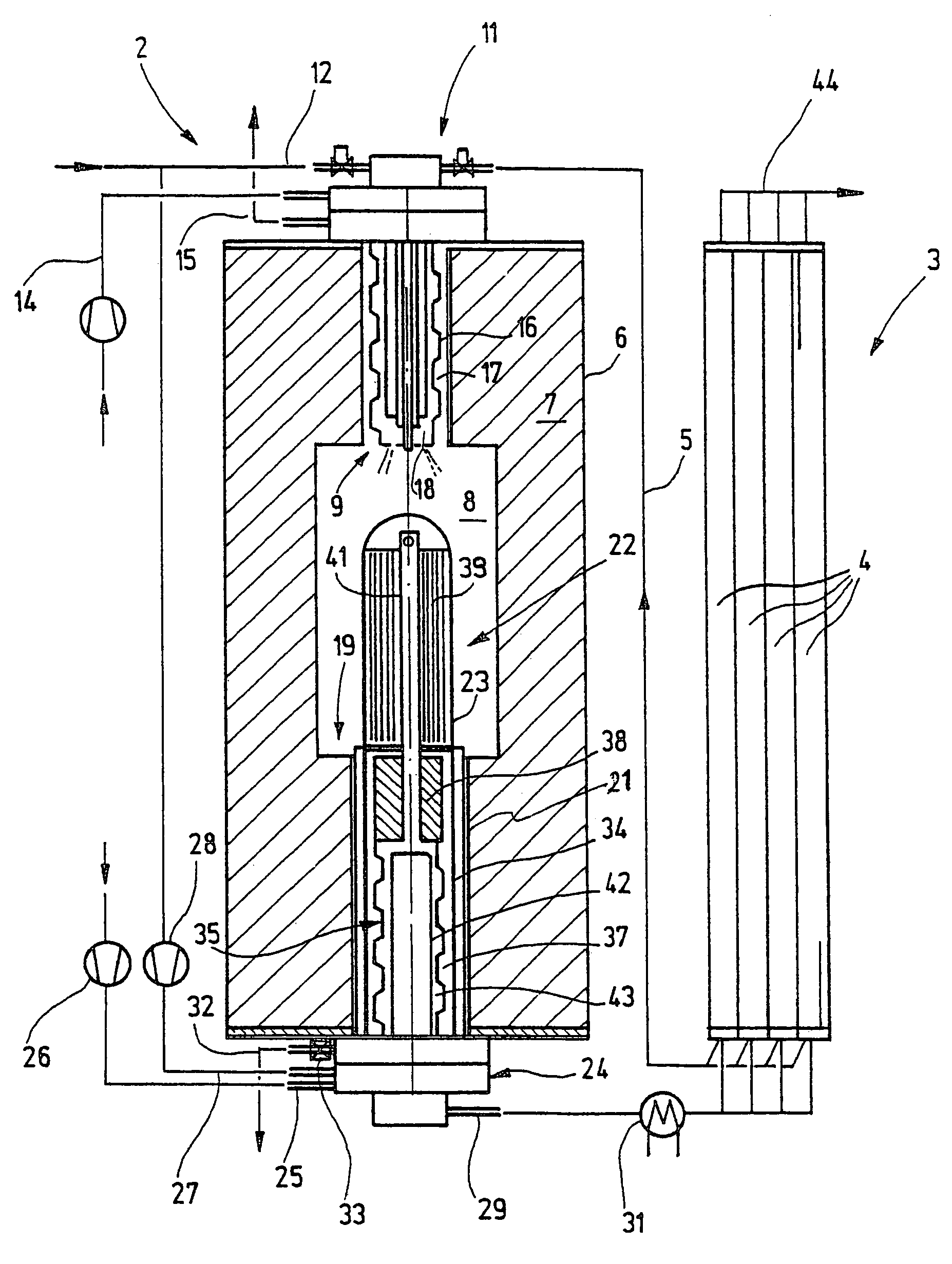
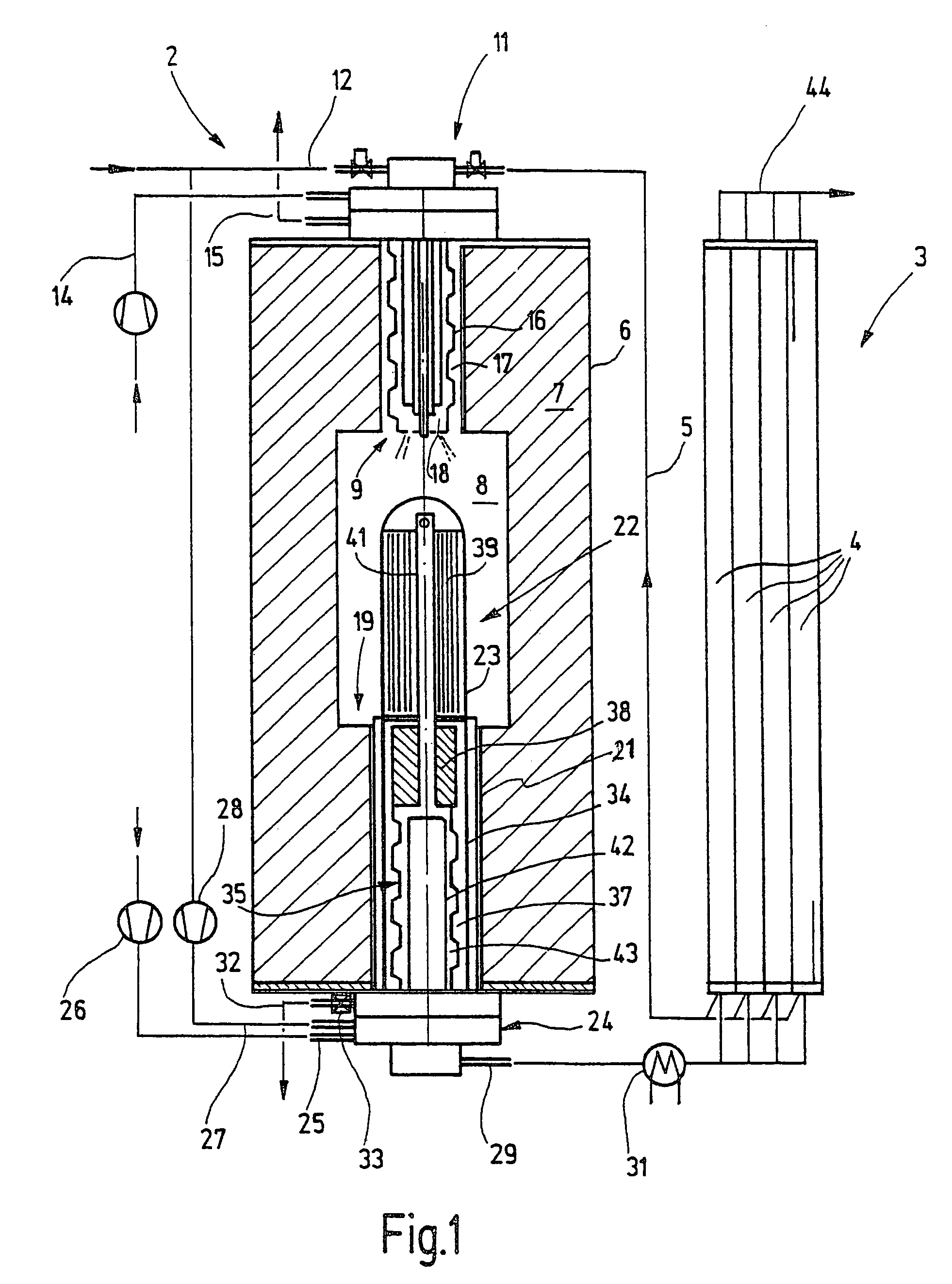
[0033]Turning to the accompanying figures, FIG. 1 shows a reforming system 1 with a reformer 2 for generating hydrogen from fuel and water. The reformer 2 is followed downstream by a pressure swing adsorption system 3 (PSA) for separating out CO. The PSA 3 has a plurality of adsorption columns 4, through which the reformate periodically flows and is back-flushed. Residual gases are delivered to the reformer 2 via a line 5.

[0034]The reformer 2 has a housing 6, for instance, a cylindrical housing, with a heat insulation jacket 7. This jacket encloses a heating or combustion chamber 8, which for instance is cylindrical, on the face end 9 of which a burner 11 is disposed. The burner 11 is connected to the line 5 and to a fuel line 12. Via a line 14, air is delivered to the burner 11. Exhaust gases leave the burner 11 via an exhaust gas line 15. The burner 11 has a recuperator 16, which on the outside defines an annular exhaust gas conduit 17 and on the inside defines an air delivery con...


PUM

PropertyMeasurementUnit
Temperatureaaaaaaaaaa
Fractionaaaaaaaaaa

Abstract

A reformer which enables rapid load changes of up to 100% within a few seconds and is intended to produce hydrogen from hydrocarbons by steam reformation, comprises an evaporator cooler for cooling the reformate and for generating steam. The evaporator cooler is disposed in the reformer, on the end of its reaction vessel. It keeps the applicable end of the tube cool and uses the waste heat of the reformate for generating steam. This makes fast load changes possible, because an increase in the introduction of water immediately causes an increase in the reformate produced and thus an increase in the heat output.

Description

[0001]This application is a national stage filing under 35 U.S.C. 371 of International Application No. PCT / DE02 / 01285, filed Apr. 9, 2002, and claims priority to German Application No. 10119083.2, filed Apr. 19, 2001.FIELD OF THE INVENTION[0002]The invention relates to a reformer for producing hydrogen and to a method for producing hydrogen from water and hydrocarbon compounds.BACKGROUND OF THE INVENTION[0003]For hydrogen generation, steam and a hydrocarbon compound (CxHy, organic compound, hydrocarbon mixture) are made to react at high temperature in a catalytic converter.[0004]European Patent Disclosure EP 0 848 989 A2 discloses a co-current or countercurrent reactor which includes a monolithic element with many conduits parallel to one another, which are divided into two groups interested with one another. The reactants (educts) flow through one group, while a mixture of combustion gas and air flows through the other. If steam is among the reactants, then it must be generated sep...

Claims


Application Information

Patent Timeline
IPC IPC(8): B01J7/00B01J8/00B01J8/02F23L15/02B01B1/00B01J8/04B01J8/06B01J19/24C01B3/32C01B3/38C01B3/48C01B3/50C01B3/56F23L15/04
CPCB01B1/005B01J8/0496B01J8/062B01J19/2485C01B3/323C01B3/382C01B3/384C01B3/48C01B3/501C01B3/56B01J8/0453C01B2203/82B01J2208/00221B01J2208/00309B01J2208/00495B01J2208/00504C01B2203/0233C01B2203/0283C01B2203/0405C01B2203/041C01B2203/043C01B2203/047C01B2203/0495C01B2203/0805C01B2203/0811C01B2203/0816C01B2203/0822C01B2203/0827C01B2203/0844C01B2203/0866C01B2203/0877C01B2203/0883C01B2203/0888C01B2203/1241C01B2203/1247C01B2203/1288C01B2203/1294C01B2203/141C01B2203/142C01B2203/145C01B2203/146C01B2203/1604C01B2203/1619Y02P20/10Y02P20/129C01B3/38
Inventor WUNNING, JOACHIM A.
Owner WS REFORMER
Why Eureka
Try Eureka