
Foamed mechanical planarization pads made with supercritical fluid

Inactive Publication Date: 2007-01-23
MICRON TECH INC
View PDF19 Cites 64 Cited by
  • Summary
  • Abstract
  • Description
  • Claims
  • Application Information

AI Technical Summary

Benefits of technology

[0014]In accordance with the invention, known methods are used to make foamed thermoplastic polymeric MP pads that are both significantly porous and uniform in porosity. In these methods according to the invention, a supercritical fluid foaming agent is dissolved in a thermoplastic polymer. A rapid decrease in solubility of the supercritical fluid foaming agent in the thermoplastic polymer and a rapid increase in volume of the supercritical fluid foaming agent in the thermoplastic polymer result in foaming of the thermoplastic polymer. In some embodiments, one or more pressure drops cause the rapid changes in solubility and in volume of the sup

Problems solved by technology

Often, imperfect substrate fabrication and imperfect integrated circuit layer deposition result in formation of undesirable topography (e.g., recesses, protrusions, scratches, etc.) on the substrate and on one or more of the deposited layers.
Because undesirable topography can compromise the integrity of an integrated circuit device (e.g., a topographical recess in a dielectric layer can impose step coverage problems with the deposition of another integrated circuit layer, undesirable topology can cause depth of focus issues during photolithography, etc.), the substrate and each deposited layer of an integrated circuit device are preferably planarized (i.e., made level) before additional layers of integrated circuit material are deposited.
However, a significantly porous MP pad may be undesirable unless the MP pad pores are both uniform in size and uniform in distribution throughout the MP pad.
Thermoset polymer MP pads may be, however, problematic.
In particular, because thermoset polymers are generally formed in thick “cakes” that are characteristically non-uniform over the surface and throughout the bulk of the cake (which is caused by a non-uniform temperature of the cake during curing of the thermoset polymer), individual thermoset polymer MP pads mechanically skived (i.e., cut) from a thermoset cake are likely to exhibit unpredictable irregularities and non-uniformity.
Further, mechanically skiving a thermoset cake can introduce surface and bulk irregularities such as, for example, fracturing and abrasions in thermoset MP pads.
Thus, thermoset polymer MP pads are often characterized by undesirable non-uniformity across the surface and throughout the bulk of a single MP pad and by undesirable non-uniformity from MP pad to pad.
Because non-uniform MP pads can produce undesirable non-uniformity in the surface of an integrated circuit wafer during polish of that wafer, it may not be desirable to use caked thermoset polymer MP pads in an MP process.
In addition, because mechanically cutting thermoset cakes to produce thermoset MP pads typically results in significant material waste (i.e., the unusable material cut from the edges of thermoset cakes), methods of fabricating thermoset MP pads from caked thermoset polymers may not be cost-effective.
Note that although single thermoset polymer MP pads may be formed via reaction injection molding (“RIM”), difficulty in controlling the ratio of components of the thermoset polymer during injection and in controlling the temperature of the thermoset polymer during thermoset polymer curing causes these pads to be especially non-uniform.
However, sintered thermoplastic polymeric MP pads may be problematic.
In particular, because dry thermoplastic resins are often imperfectly mechanically ground to a predetermined size before they are sintered, and because slight variations in resin size can result in undesirably non-uniform pores, sintered thermoplastic polymeric MP pads can be undesirably non-uniformly porous.
Further, uneven pressure and uneven distribution of dry thermoplastic resins in an MP pad mold can result in sintered thermoplastic polymeric MP pads that are non-uniformly porous.
However, because the thermoplastic pad derives its porosity from the projecting ends of the porous network, and because these projecting ends are somewhat randomly distributed, thermoplastic MP pads made by coalescing thermoplastic polymer with felt or woven fiber are often non-uniformly porous.
In the known methods, a rapid change in the solubility and volume of a supercritical fluid dissolved in a thermoplastic polymer results in foaming of the thermoplastic polymer.
However, such methods are not known for fabricating MP pads.

Method used


Image

  • Foamed mechanical planarization pads made with supercritical fluid
  • Foamed mechanical planarization pads made with supercritical fluid
  • Foamed mechanical planarization pads made with supercritical fluid

Examples


Embodiment Construction

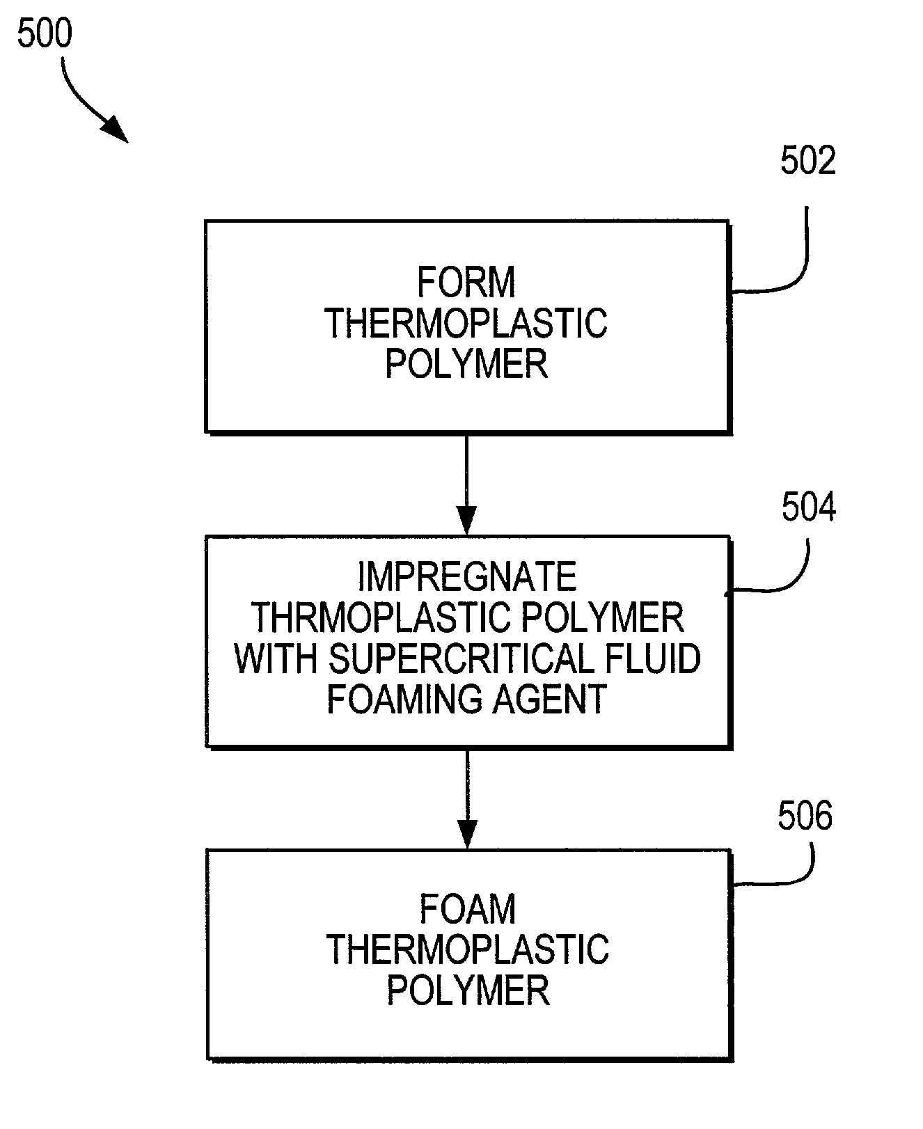
[0024]The invention uses known methods of fabricating foamed thermoplastic polymeric materials using supercritical fluids to fabricate thermoplastic polymeric mechanical planarization (“MP”) polishing pads.

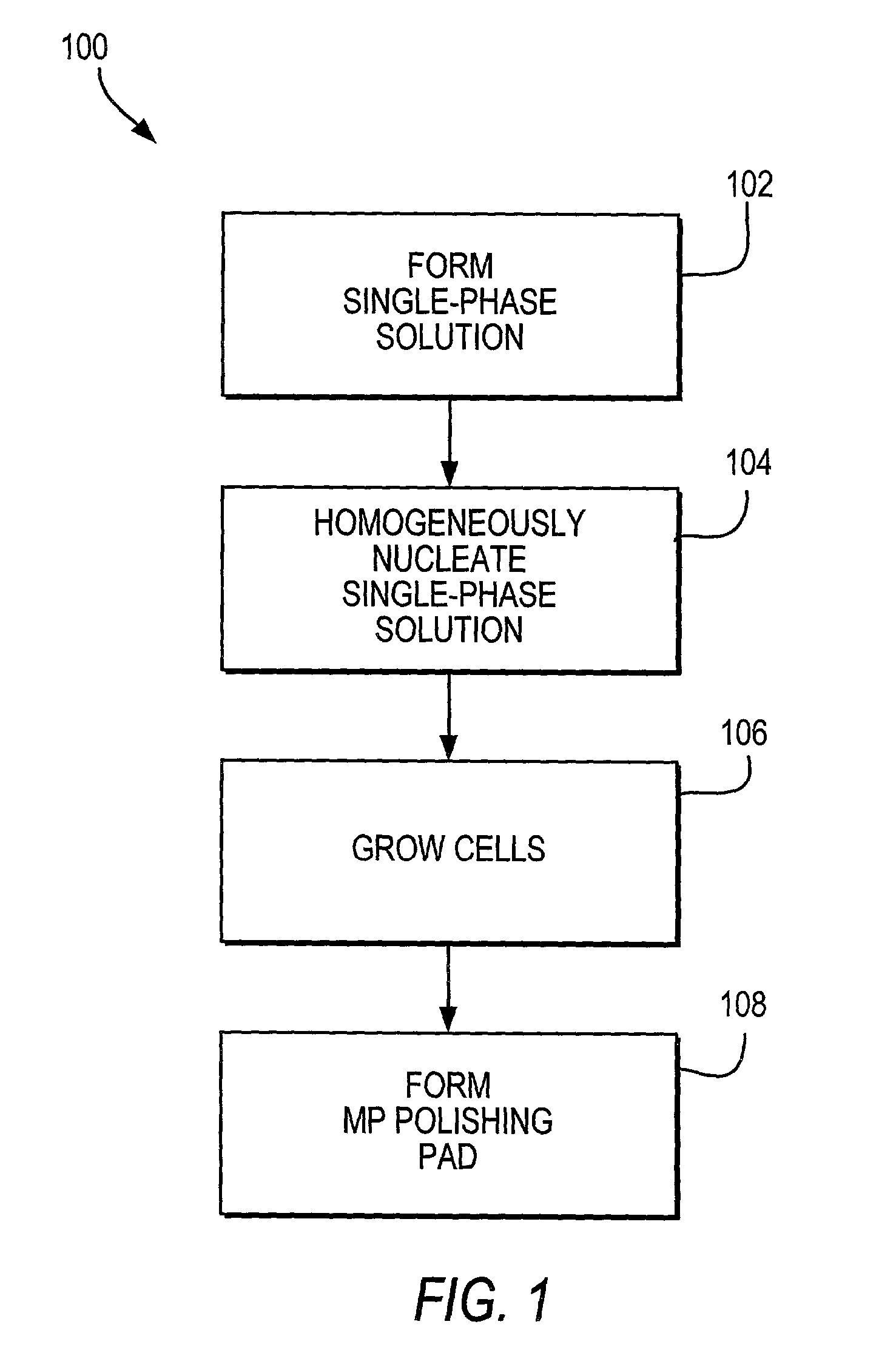
[0025]FIG. 1 shows an exemplary method 100 for fabricating foamed thermoplastic polymeric MP pads using supercritical fluid in accordance with the invention. At step 102, a single-phase solution consisting essentially of a molten thermoplastic polymer and a supercritical fluid foaming agent is formed. A supercritical fluid is a material that is concurrently maintained at temperatures and pressures exceeding the critical temperature (Tc) and critical pressure (Pc) of the material. The supercritical fluid foaming agent is preferably supercritical carbon dioxide (Tc=31.1° C., Pc=1071.3 psi) or supercritical nitrogen (Tc=−147.0° C., Pc=492.3 psi), but may be any other supercritical fluid that is gaseous under obtainable MP pad processing conditions and that readily dissolves in a ther...


PUM

PropertyMeasurementUnit
Temperatureaaaaaaaaaa
Pressureaaaaaaaaaa
Densityaaaaaaaaaa

Abstract

Foamed thermoplastic polymeric mechanical planarization polishing pads (“MP pads”) made with supercritical fluids are presented. A supercritical fluid foaming agent is dissolved in a thermoplastic polymer. A rapid change in the solubility and volume of the supercritical fluid foaming agent in the thermoplastic polymer results in foaming of the thermoplastic polymer. Foamed thermoplastic polymeric MP pads are advantageously both significantly and uniformly porous.

Description

BACKGROUND OF THE INVENTION[0001]This invention relates to uniformly-foamed thermoplastic polymeric mechanical planarization polishing pads (“MP pads”). More particularly, this invention relates to uniformly-foamed thermoplastic polymeric MP pads made with supercritical fluids.[0002]Multiple layers of conducting, semiconducting, dielectric, and insulating materials are deposited on a substrate during integrated circuit device fabrication. Often, imperfect substrate fabrication and imperfect integrated circuit layer deposition result in formation of undesirable topography (e.g., recesses, protrusions, scratches, etc.) on the substrate and on one or more of the deposited layers. Because undesirable topography can compromise the integrity of an integrated circuit device (e.g., a topographical recess in a dielectric layer can impose step coverage problems with the deposition of another integrated circuit layer, undesirable topology can cause depth of focus issues during photolithography...

Claims


Application Information

Patent Timeline
IPC IPC(8): B29C44/02B29C44/34H01L21/00
CPCB29C44/3453H01L21/6715B29C44/348
Inventor KRAMER, STEPHEN J
Owner MICRON TECH INC
Features
  • Generate Ideas
  • Intellectual Property
  • Life Sciences
  • Materials
  • Tech Scout
  • Unparalleled Data Quality
  • Higher Quality Content
  • 60% Fewer Hallucinations
Learn More