Method for controlling a windscreen-wiping device, and windscreen-wiping device for a motor vehicle

Active Publication Date: 2007-01-23
ROBERT BOSCH GMBH
View PDF10 Cites 37 Cited by
  • Summary
  • Abstract
  • Description
  • Claims
  • Application Information

AI Technical Summary

Benefits of technology

[0007]It is also advantageous if the drive device consumes a current I, and the torque is effected by a limitation of the current I. In this way, the torque can be limited by means of a simple current limiter.
[0008]Advantageously, the limitation of the current I is effected by a characteristic curve that is stored in memory in the control unit, as a result of which a completely freely selectable current limitation as a function of the gear position is made possible.
[0009]It is furthermore advantageous if the drive device is controlled electronically and has a position and/or rotary motion detector, so that the current limitation can be adapted exactly to the current gear position.
[0010]It is especially advantageous if the drive device is embodied as a reversing motor, and after the turning point is reached, a higher torque is output by the drive device than before the one turning point is reached, in order

Problems solved by technology

Such blockage is especially problematic if blockage of the wiper syst

Method used


Image

  • Method for controlling a windscreen-wiping device, and windscreen-wiping device for a motor vehicle
  • Method for controlling a windscreen-wiping device, and windscreen-wiping device for a motor vehicle
  • Method for controlling a windscreen-wiping device, and windscreen-wiping device for a motor vehicle

Examples


Example

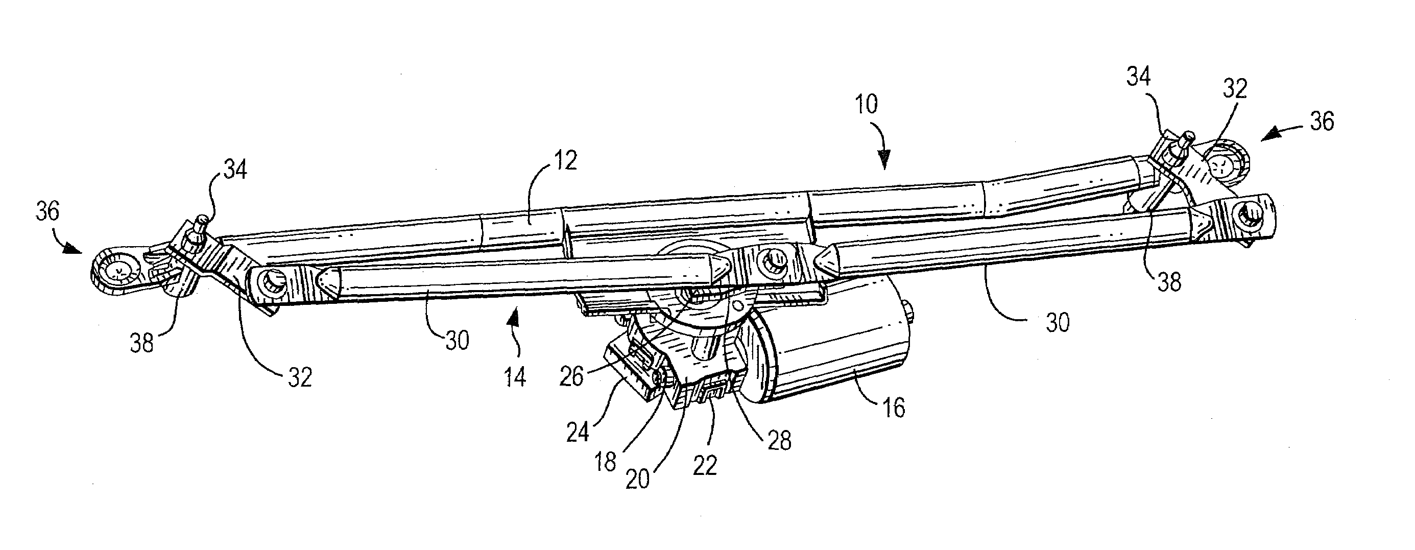
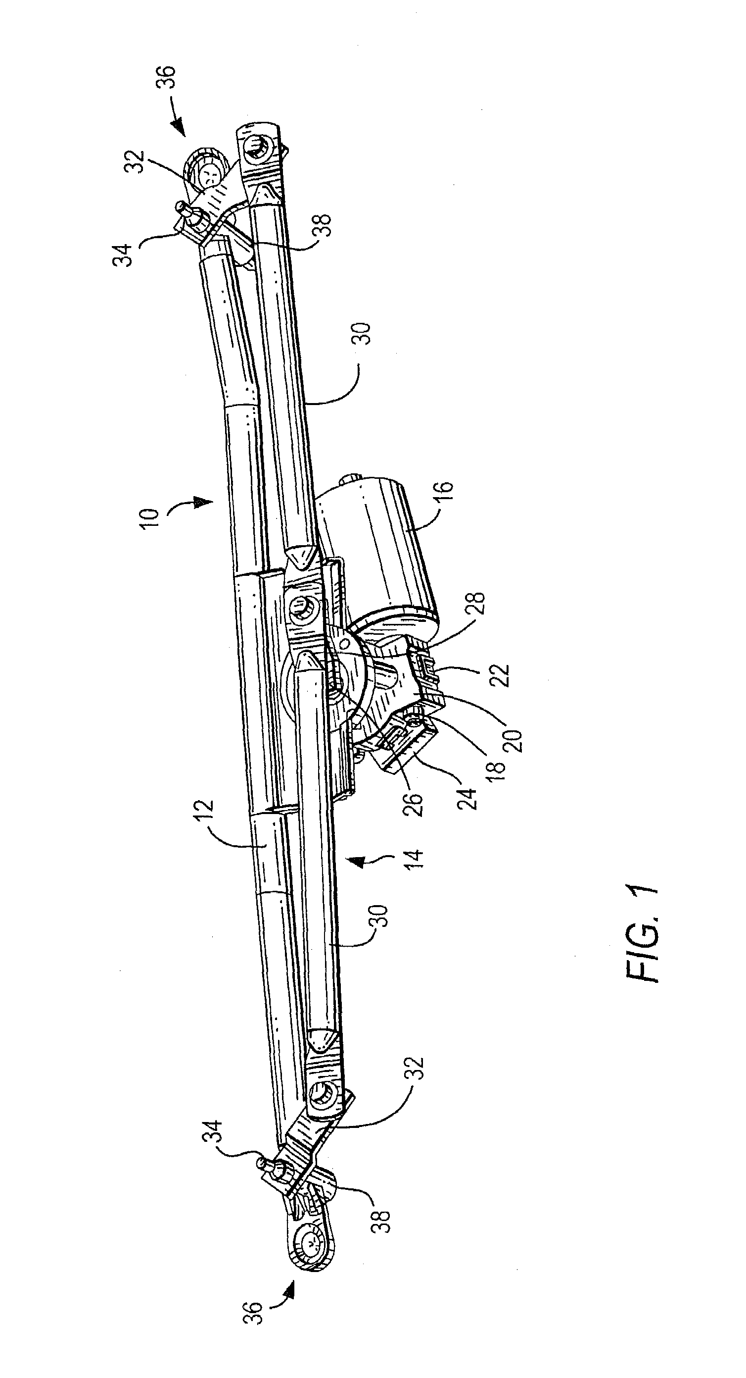
[0018]In FIG. 1, a wiper system 10 of the invention is shown in perspective. It essentially comprises a support tube 12, a gear 14, and a drive device 16. The drive device 16 is embodied as an electric motor, which may be in the form of a reversing motor or a revolving motor. The drive device 16 has an armature shaft 18, which drives a motor gear 20. The motor gear 20 is disposed in a motor gearbox 22, which is covered by a lid in which an open-loop control unit 24 is located. The motor gear 20 drives the gear 14 via a driven shaft 26. To that end, the gear 14 has a motor crank 28, which moves a thrust rod 30 that is rotatably joined to it.

[0019]If the drive device 16 is embodied as a reversing motor, then when current is supplied to the drive device, the motor crank 28 swings back and forth in pendulum fashion between two angular positions. In the case of a revolving motor, the motor crank 28 executes a revolving rotary motion.

[0020]Since the wiper system shown here is meant to dri...


PUM


Abstract

A method for the open-loop control of a wiper system (10), and a wiper system (10), in particular for a motor vehicle includes at least one drive device (16), at least one gear (14), which switches the motion of the drive device (16) to at least one wiper shaft (34) and has a gear ratio that depends on the position of the gear (14), and at least one open-loop control unit (24), which controls the torque that can be output by the drive device (16) by means of a driven shaft (26). The control unit (24) determines the torque that can be output by the drive device (16) at every instant, taking the gear ratio into account.

Description

CROSS-REFERENCE[0001]The invention described and claimed hereinbelow is also described in PCT / DE 02 / 02171, filed on Jun. 14, 2002 and DE 101 44985.2, filed Sep. 12, 2001. This German Patent Application provides the basis for a claim of priority of invention under 35 U.S.C. 119 (a)–(d).BACKGROUND OF THE INVENTION[0002]The invention relates to a wiper system and a method for open-loop control of a wiper system.[0003]Numerous methods for open-loop control of wiper systems are known, for instance from German Patent Disclosure DE 197 00 457. In these methods, the wiper motor in each case is triggered such that the position of the wiper blade on the window always move along a desired trajectory. In simpler methods, the speed of the wiper motor and thus the speed of the wiper blade on the window is reduced in the region of the turning points. However, this involves commonly used closed-loop control mechanisms for positionally accurate control of the wiper blade.SUMMARY OF THE INVENTION[000...

Claims


Application Information

Patent Timeline
IPC IPC(8): B60S1/08
CPCB60S1/08Y10S318/02B60S1/18
Inventor ZIMMER, JOACHIM
Owner ROBERT BOSCH GMBH
Why Eureka
Try Eureka