Silicon-based electro-optic phase modulator with reduced residual amplitude modulation

a phase modulator and electro-optic technology, applied in the field of silicon-based electro-optic phase modulators, can solve the problems of unwanted amplitude modulation and affecting the amplitude of optical signals, and achieve the effect of improving the shape of phase and amplitude responses

Active Publication Date: 2007-01-23
CISCO TECH INC
View PDF5 Cites 9 Cited by
  • Summary
  • Abstract
  • Description
  • Claims
  • Application Information

AI Technical Summary

Benefits of technology

[0008]In accordance with the present invention, a filtering arrangement is formed that includes at least a pair of filters, a first filter biased at a near linear region of the amplitude response (positive or negative) and a second filter biased at the opposing near linear region (i.e., negative or positive, respectively). Presuming the first filter is biased along the negative slope region, the amplitude response curve shifts to exhibit more delay and the amplitude is reduced. The second filter, in this case, is biased along the positive slope region so as to increase the amplitude. By controlling the bias points for these two filters, therefore a “zero” amplitude response can be achieved, allowing for pure phase modulation to be provided.
[0010]In general, a plurality of such filtering elements may be used in combination, where the additional number of elements serves to improve the shape of both the phase and amplitude responses of the modulator by increasing the number of poles and zeroes in the filter response.

Problems solved by technology

However, a problem arises with such modulators that are based on the free carrier effect to provide the desired modulation.
As a result, the application of a signal to modulate the phase of the optical signal will also affect the amplitude of the optical signal.
This is problematic in that the unwanted amplitude modulation introduces error in the output signal. FIG. 3 illustrates the presence of this amplitude modulation and the residual AM modulated signal components in the associated frequency spectrum.

Method used


Image

  • Silicon-based electro-optic phase modulator with reduced residual amplitude modulation
  • Silicon-based electro-optic phase modulator with reduced residual amplitude modulation
  • Silicon-based electro-optic phase modulator with reduced residual amplitude modulation

Examples


Embodiment Construction

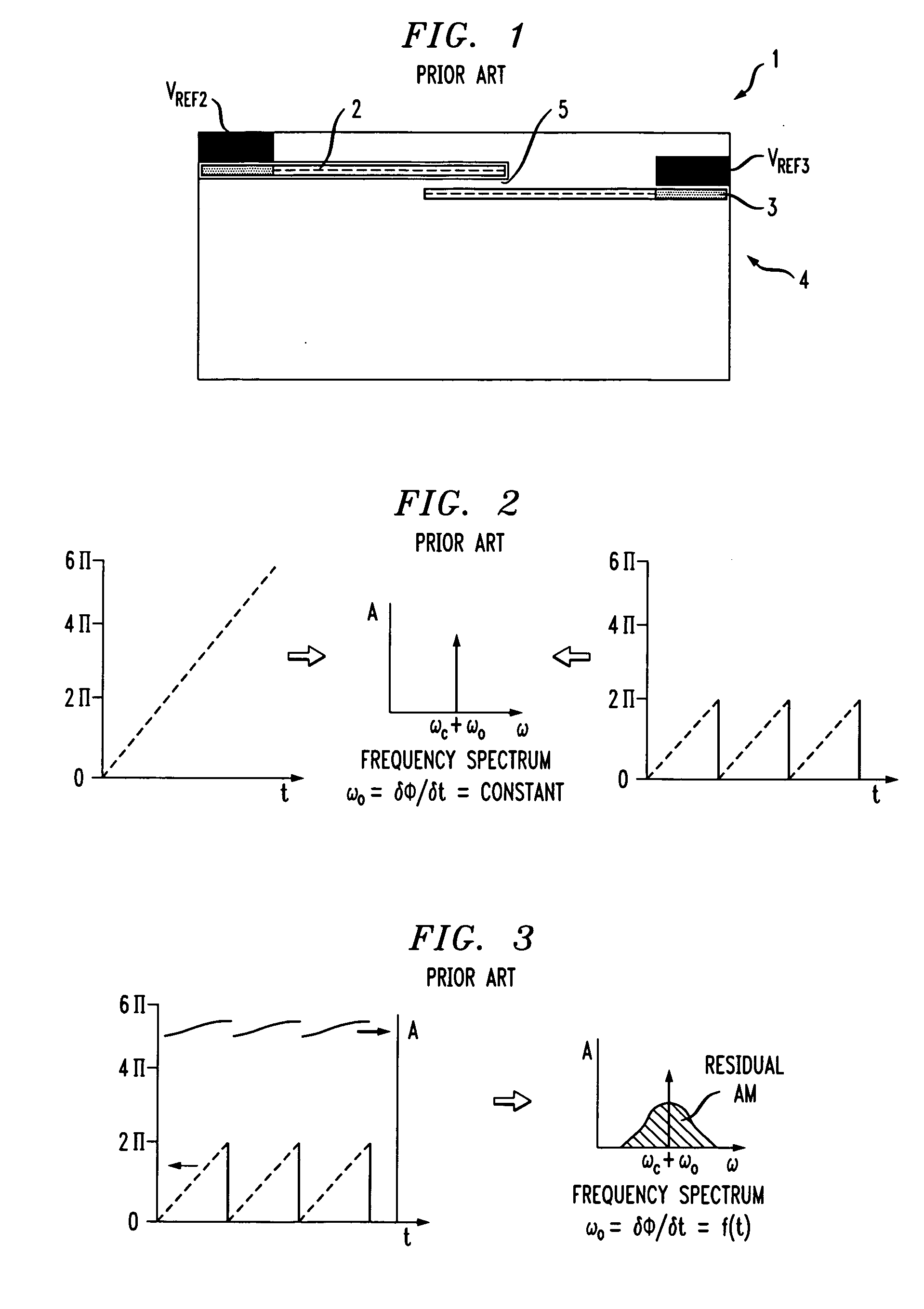
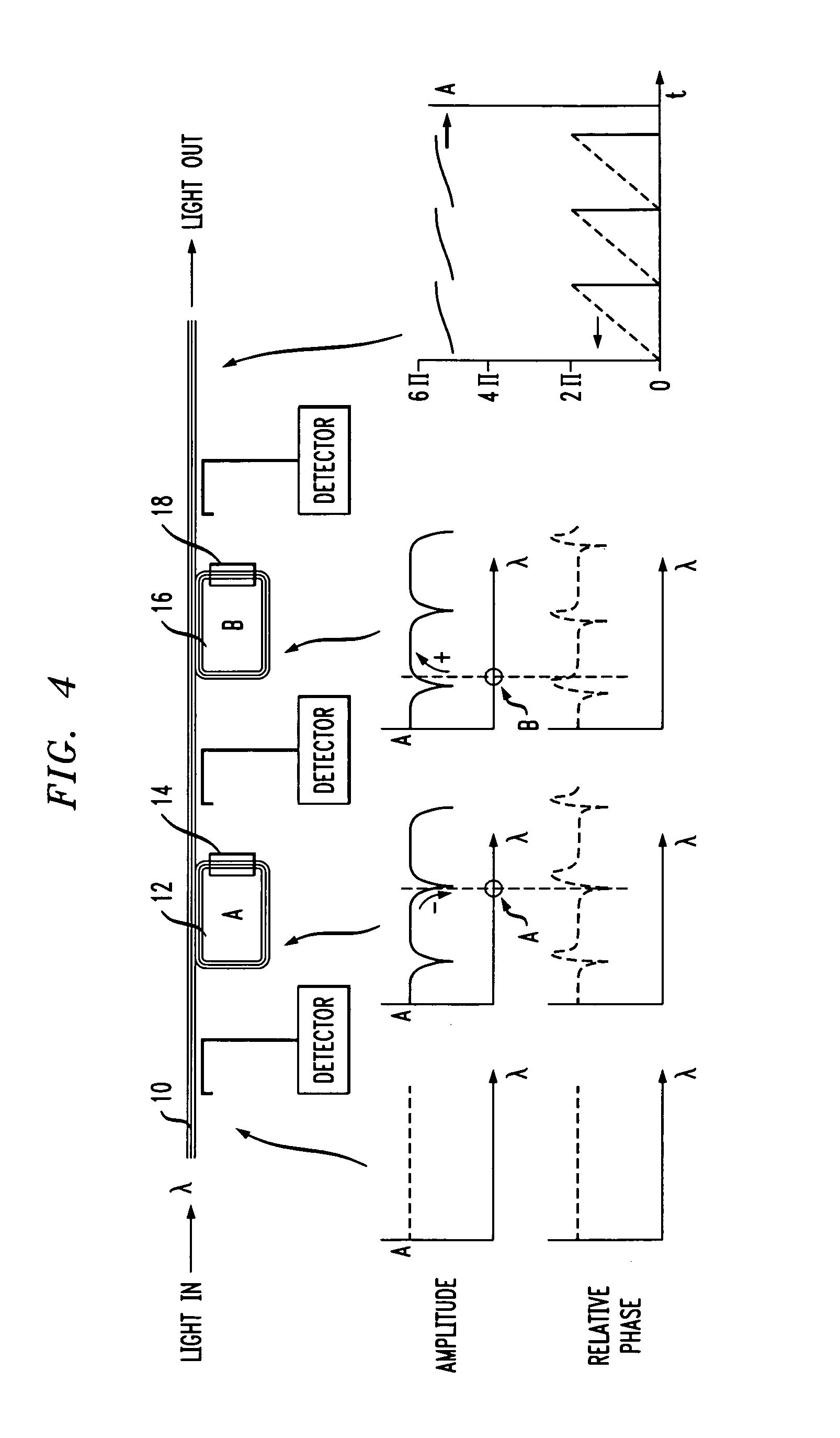
[0019]An exemplary arrangement for substantially reducing the presence of amplitude modulation in a phase modulated output signal O from an electro-optic modulator is illustrated in FIG. 4. As shown, optical signal O is propagating along a waveguide 10, where in most cases waveguide 10 will comprise a relatively thin (less than one micron) silicon surface layer of a silicon-on-insulator (SOI) structure. Moreover, the “active region” of waveguide 10 is best confined in the manner described above in association with FIG. 1, which illustrates an “active region”5 having a relatively narrow width. Such an arrangement is important for single mode applications.

[0020]Referring again to FIG. 4, a first optical filtering element 12 (in this case, a ring waveguide) is disposed along waveguide 10 in a manner so as to out-couple a selected portion of the propagating signal. The Q of the ring (and as a result, the phase) defines the selectivity of the filter, where the higher the Q factor, the mo...


PUM

PropertyMeasurementUnit
wavelengthaaaaaaaaaa
phaseaaaaaaaaaa
difference wavelengthaaaaaaaaaa

Abstract

An arrangement for removing unwanted amplitude modulation from the output of an electro-optic phase modulator (formed within a silicon-on-insulator (SOI) system) includes resonant filters that are biased on the positive and negative slopes of the response signal. Therefore, as the amplitude response of one filter decreases, the amplitude response of the other filter increases, resulting in balancing the output and essentially eliminating amplitude modulation from the phase-modulated output signal. In one embodiment, ring resonators (formed in the SOI layer) are used to provide the filtering, where as the number of resonators is increased, the performance of the filtering arrangement is improved accordingly.

Description

CROSS-REFERENCE TO RELATED APPLICATIONS[0001]This application claims the benefit of U.S. Provisional Application No. 60 / 652,608, filed Jan. 28, 2005.TECHNICAL FIELD[0002]The present, invention relates to a silicon-based electro-optic phase modulator and, more particularly, to a modulator formed within a silicon-on-insulator (SOI) structure and incorporating tunable ring filters to essentially “cancel” the (unwanted) amplitude modulation present on the modulated optical output signal.BACKGROUND OF THE INVENTION[0003]Significant advances in the ability to provide optical modulation in a silicon-based platform has been made, as disclosed in U.S. Pat. No. 6,845,198, issued to R. K. Montgomery et al. on Jan. 18, 2005 and assigned to the assignee of the present application. The Montgomery et al. modulator is based on forming a gate region of a first conductivity type to partially overlap a body region of a second conductivity type, with a relatively thin dielectric layer interposed betwee...

Claims


Application Information

Patent Timeline
Patent Type & Authority Patents(United States)
IPC IPC(8): G02F1/03G02F1/01G02F1/035
CPCG02F1/2257G02F2203/15G02F1/3519
Inventor PIEDE, DAVID
Owner CISCO TECH INC
Why Eureka
Try Eureka