

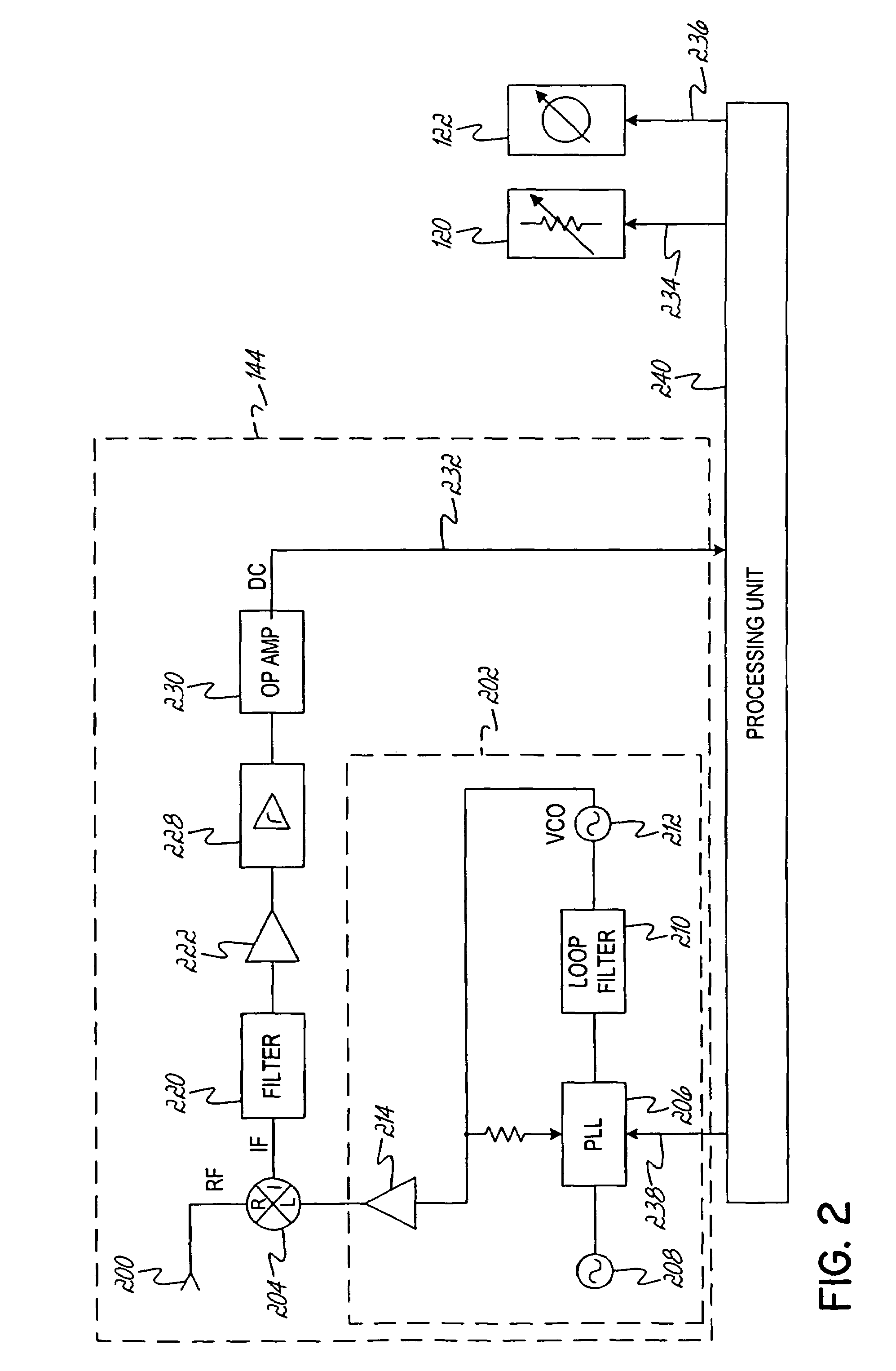
Scanning receiver for use in power amplifier linearization
a linear amplifier and receiver technology, applied in the field of radio frequency (rf) power amplifiers, can solve the problems of unwanted imd, difficult linear amplifier design, and disrupt the proper transmission and reception of rf signals
- Summary
- Abstract
- Description
- Claims
- Application Information
AI Technical Summary
Benefits of technology
Problems solved by technology
Method used
Image

Examples
Embodiment Construction
[0015]Although the invention will be described next in connection with certain embodiments, it will be understood that the invention is not limited to those particular embodiments. On the contrary, the description of the invention is intended to cover all alternatives, modifications, and equivalent arrangements as may be included within the spirit and scope of the invention as defined by the appended claims.
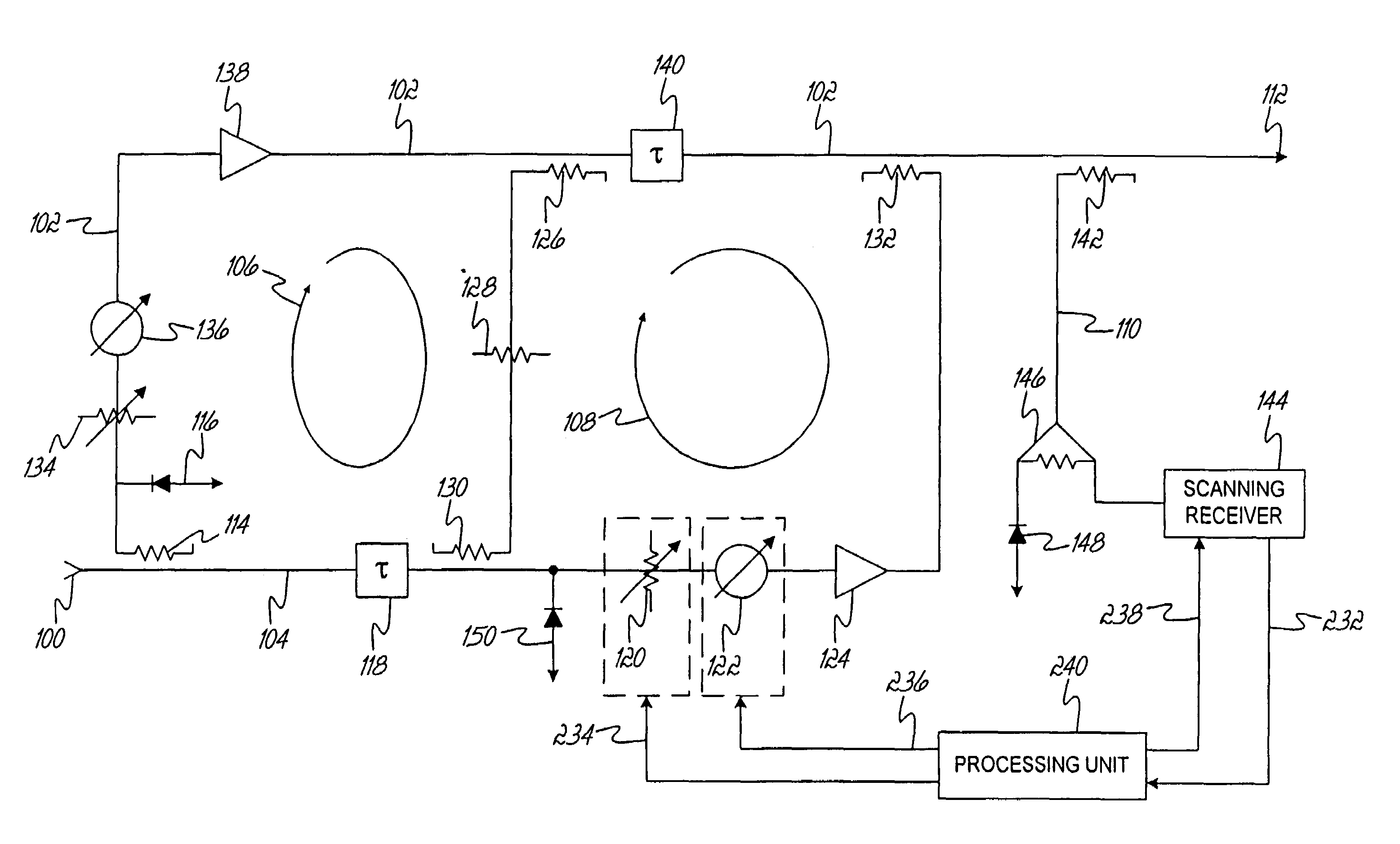
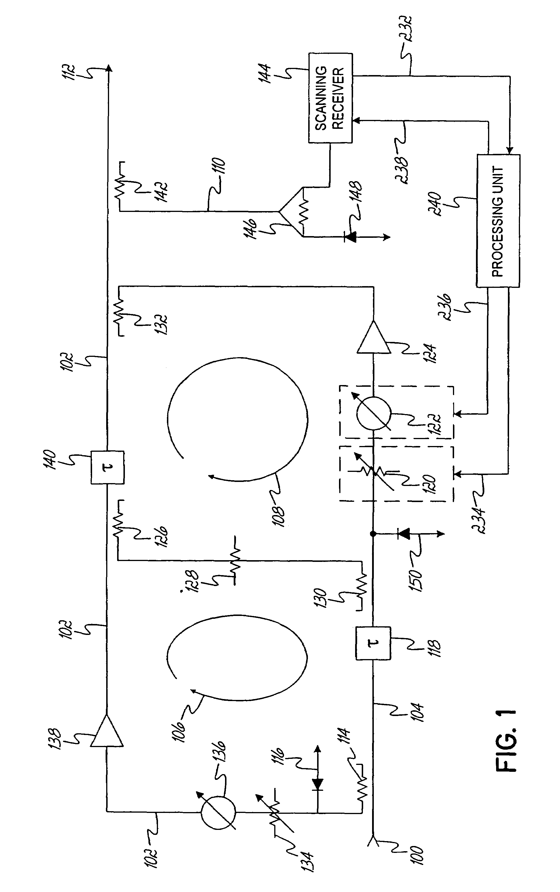
[0016]The present invention relates to a method and apparatus for locating and suppressing intermodulation distortion (IMD) products in a power amplifier system. In the embodiments described hereinafter, IMD products are suppressed in a feed forward multi-carrier power amplifier system. However, as will become apparent below, the principles of the invention may apply to single-carrier power amplifier systems, as well as to power amplifier systems incorporating other linearization schemes, e.g., predistortion amplifiers, Envelope Elimination and Restoration (EER) amplifiers, and v...
PUM
 Abstract
Description
Claims
Application Information