Eulerian-Lagrangian mapping for finite element analysis

a finite element analysis and lagrangian mapping technology, applied in the field of computer simulations using the finite element method, can solve the problems of distorted elements, inability to accurately integrate, and general over-complexity of equations describing the physical event of interest to be solved exactly

Active Publication Date: 2007-01-23
ANSYS
View PDF7 Cites 39 Cited by
  • Summary
  • Abstract
  • Description
  • Claims
  • Application Information

AI Technical Summary

Benefits of technology

[0019]The present invention includes a method that overcomes the disadvantages of conventional finite element simulations. The method accomplishes this by switching from an Eulerian to a Lagrangian formulation during a finite element simulation. The material and void based Eulerian formulation is suitable for the study of mechanical processes involving large deformations. An implicit Lagrangian formulation is preferable for the treatment of quasi-static and small deformation processes.

Problems solved by technology

The equations describing the physical event of interest are generally overly complex to be solved exactly.
Due to non-linearities, an exact integration is generally not possible.
Distorted elements are bad for the numerical accuracy and can even lead to crashing simulations.
A disadvantage is that the flux of material between elements (fixed in space) slows down the simulation and is bad for numerical accuracy.
Another disadvantage is that the need for stability in the explicit time integration scheme puts a limit on the maximum allowed time step size.
A disadvantage of the Lagrangian formulation is that element distortions cause numerical problems when dealing with large deformations.
Further, solving complex equation systems makes each time step rather costly in terms of time and computing resources.

Method used


Image

  • Eulerian-Lagrangian mapping for finite element analysis
  • Eulerian-Lagrangian mapping for finite element analysis
  • Eulerian-Lagrangian mapping for finite element analysis

Examples


Embodiment Construction

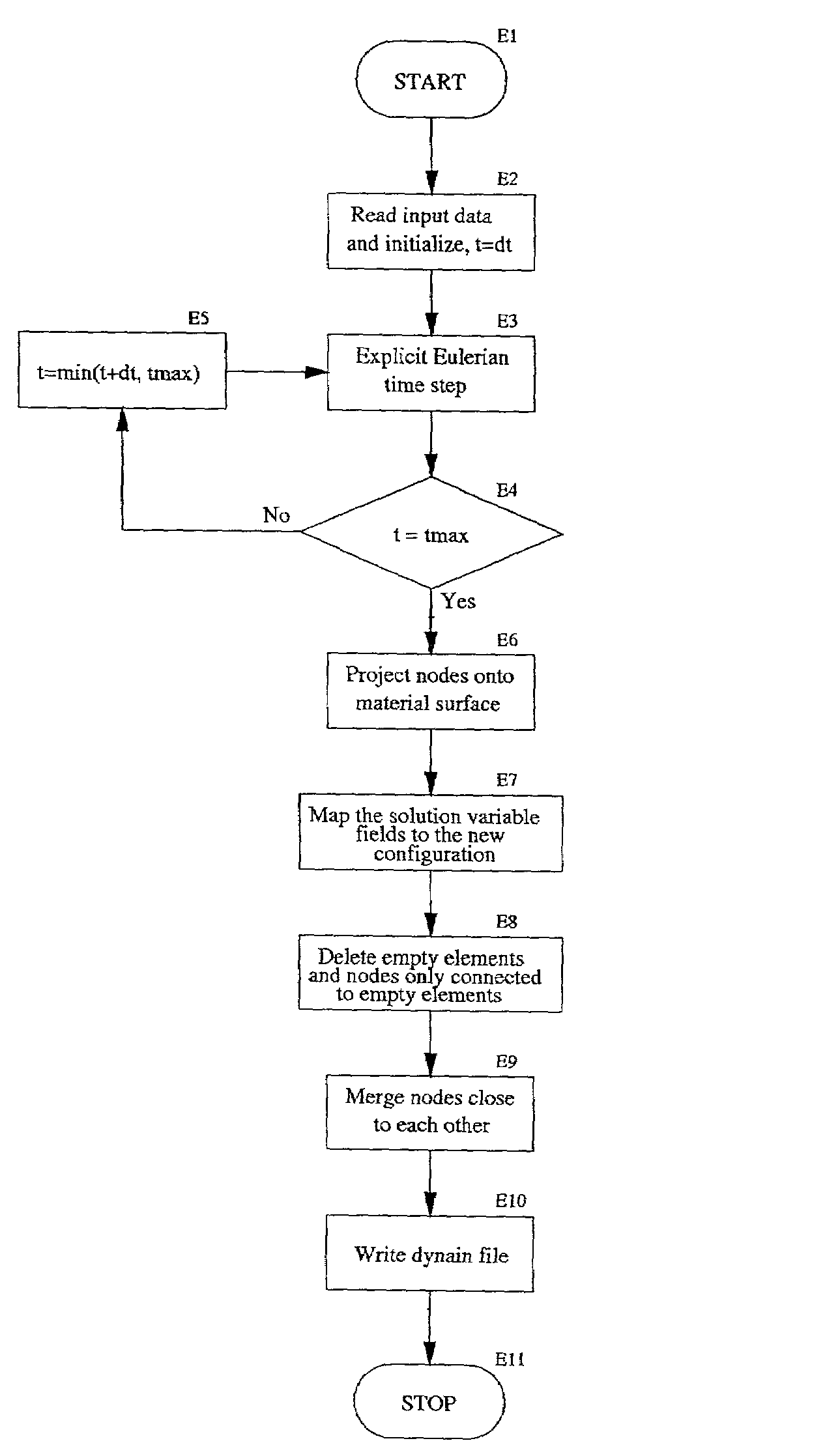
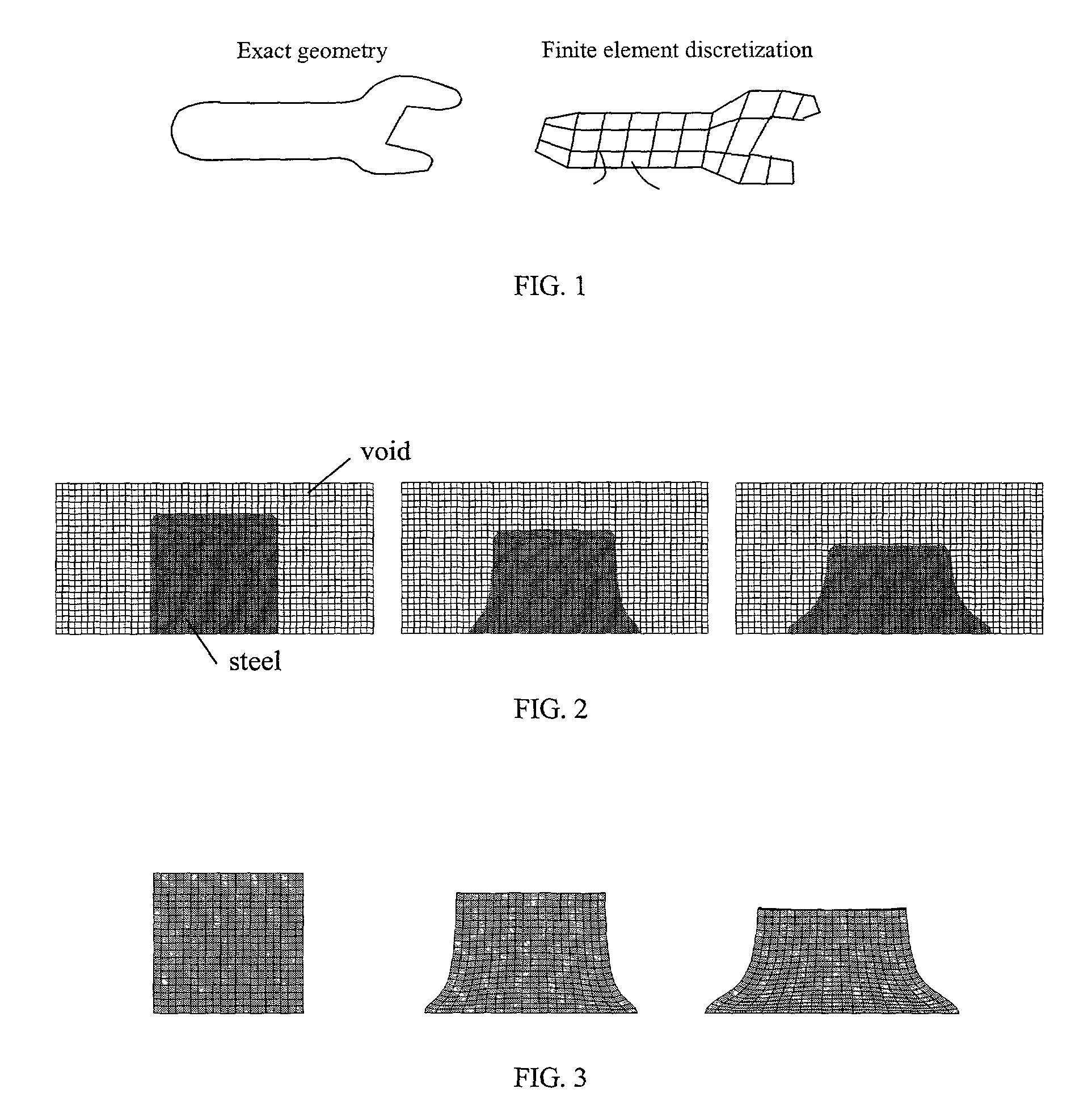
[0040]The preferred embodiments of the present invention and their advantages are best understood by referring to FIGS. 1 through 5 of the drawings. Like numerals are used for like and corresponding parts of the various drawings.

System Overview

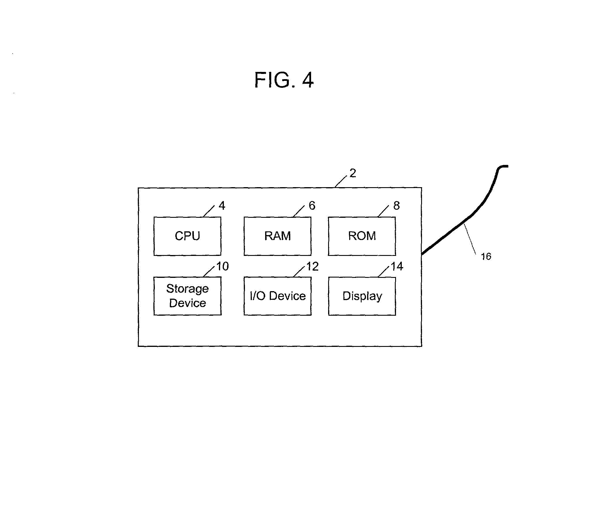
[0041]FIG. 4 is a block diagram of an exemplary computer system 2 upon which the methods of the present invention can be performed, according to an embodiment of the present invention. Computer system 2 can include one or more suitable processing facilities such as microcomputers / workstations, minicomputers, mainframes, and / or massively parallel processing computers running suitable operating systems. Examples of suitable microcomputers / workstations include the IBM PC from IBM Corporation of Armonk, N.Y., and the Sparc-Station from Sun Microsystems Corporation of Mountain View, Calif. Examples of suitable minicomputers are the VAX 750 from Digital Equipment Corporation of Maynard, Mass. and the AS / 400 from IBM. An example of a suitable mainfra...


PUM


Abstract

A computer system and method for performing a finite element analysis to determine the final dimensions of an object comprising automatically switching from an Eulerian formulation to a Lagrangian formulation during the analysis.

Description

CROSS REFERENCE TO RELATED APPLICATIONS[0001]This application is related to U.S. patent application Ser. No. 09 / 836,490 filed Apr. 17, 2001 entitled “Implicit-Explicit Switching for Finite Element Analysis”, which is hereby incorporated by reference in its entirety.BACKGROUND OF THE INVENTION[0002]1. Field of the Invention[0003]The present invention relates generally to computer simulations using the finite element method, and more specifically, to a method for switching from an explicit Eulerian formulation to an implicit Lagrangian formulation in a finite element simulation of motion.[0004]2. Related Art[0005]The finite element method is a technique for obtaining approximate numerical solutions to boundary value problems which predict the response of physical systems subjected to external loads. The finite element method is described in detail by Thomas J. R. Hughes in “The Finite Element Method” (1987), published by Prentice-Hall, Inc., New Jersey, which is incorporated herein by...

Claims


Application Information

Patent Timeline
Patent Type & Authority Patents(United States)
IPC IPC(8): G06F17/50
CPCG06T17/20G06F17/5018G06F30/23
Inventor OLOVSSON, LARS
Owner ANSYS
Why Eureka
Try Eureka