
High pressure pump piston

a high-pressure piston and pump technology, applied in the direction of machines/engines, braking systems, liquid fuel engines, etc., to achieve the effect of reducing the extrusion of seal elastomers, reducing the force per unit area of bearing surfaces, and facilitating four functions

Inactive Publication Date: 2007-01-30
NOVATECH HLDG CORP
View PDF7 Cites 14 Cited by
  • Summary
  • Abstract
  • Description
  • Claims
  • Application Information

AI Technical Summary

Benefits of technology

The design significantly reduces seal extrusion and frictional heat, extending piston service life and reducing liner wear, while maintaining efficient operation under high pressures.

Problems solved by technology

In particular, test specimens of seal elastomer have demonstrated unexpectedly strong adhesion to specimens of a filled-polymer bearing ring comprising polyamide and molybdenum disulfide, without the use of separate adhesive agents.

Method used


Image

  • High pressure pump piston
  • High pressure pump piston
  • High pressure pump piston

Examples


Embodiment Construction

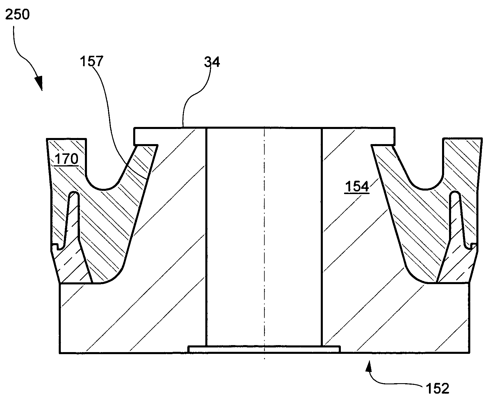
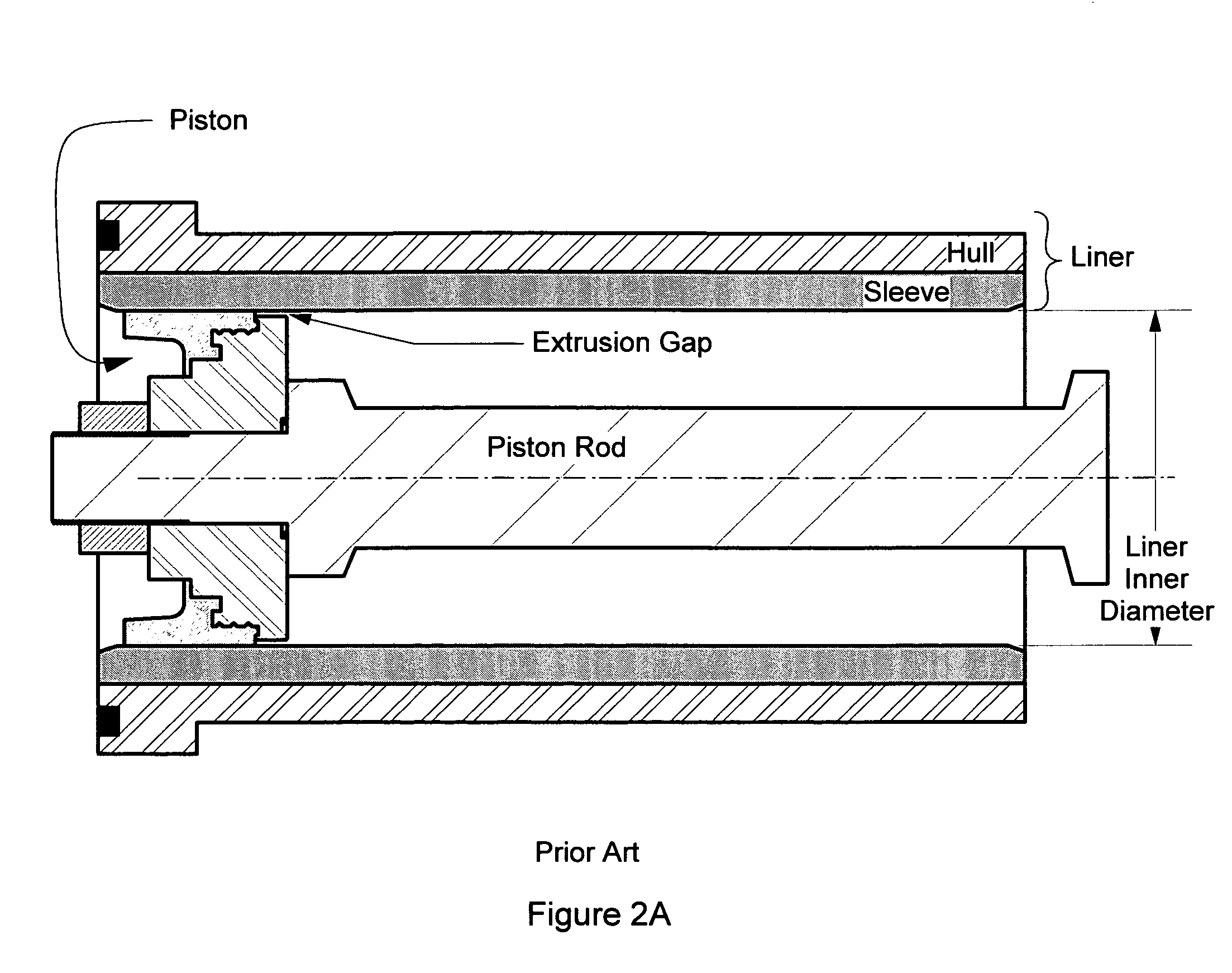
[0044]FIG. 3 schematically illustrates a cross section of a high pressure piston 50 for use within a liner for a reciprocating pump. The liner has a liner inner diameter (shown schematically in FIG. 2A) and the piston 50 comprises a metallic hub 52 symmetrical about a longitudinal axis. The hub 52 comprises a proximal transverse flange 56 having a first outer diameter D1 and a core section 54 extending distally from flange 56 to core section transverse mating surface 55. Core section 54 also extends radially less than the first outer diameter D1 to a core section peripheral surface 57. Hub 52 has a central bore 51 extending longitudinally through proximal transverse flange 56 and core section 54 for accommodating a piston rod. Core section peripheral surface 57 is shown in FIG. 3 as being frusto-conical in shape.

[0045]Piston 50 further comprises a metallic or filled-polymer bearing ring 40 having a generally annular shape with a salient outer surface and surrounding at least a porti...


PUM


Abstract

A high pressure piston for use within a liner for a reciprocating pump comprises an elastomeric seal and an annular bearing ring. During the pump's pressure stroke at least a portion of the bearing ring elastically expands radially to narrow or close the extrusion gap, thus tending to block elastomer extrusion and establish sliding contact between the bearing ring's outer surface and the liner. An extrusion control groove located radially inward from the peripheral bearing ring contact surface of certain embodiments also tends to block elastomer extrusion. Under reduced pressure on the pump's return stroke, the bearing ring elastically contracts radially, slightly widening the extrusion gap. On the pump's return stroke the slightly wider extrusion gap allows cooling water directed generally toward the proximal flange of the piston hub to better cleanse, as well as cool, the liner wall.

Description

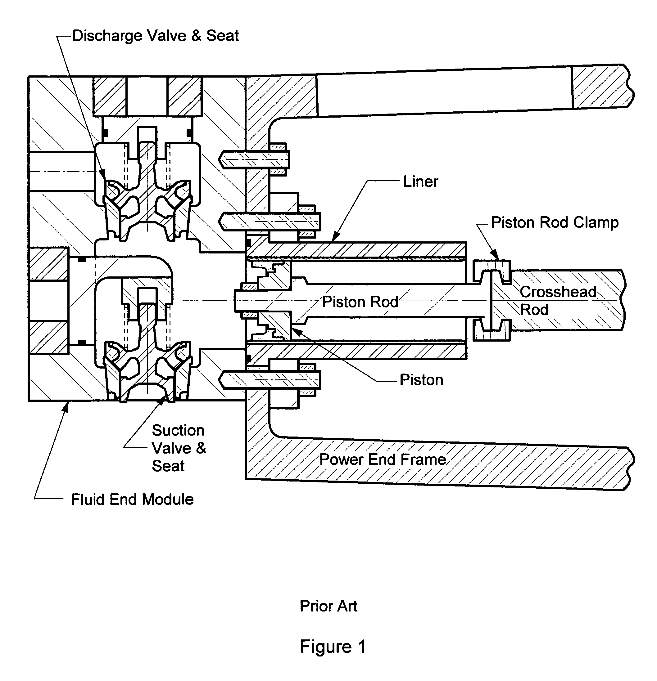
[0001]This is a continuation-in-part (CIP) patent application of application Ser. No. 10 / 838,567 having the filing date May 4, 2004 now U.S. Pat. No. 6,957,605.FIELD OF THE INVENTION[0002]The invention relates generally to high-pressure piston pumps used, for example, in oil field drilling operations. The illustrated embodiment of the invention applies to mud pumps that incorporate structural features providing for reduced piston and liner wear and increased service life.BACKGROUND[0003]Engineers typically design high-pressure oil field pumps in two sections; the (proximal) power section (herein “power end”) and the (distal) fluid section (herein “fluid end”). The power end usually comprises a crankshaft, reduction gears, bearings, connecting rods, crossheads, crosshead extension rods, etc. Also located in the power end of a mud pump is at least one liner within which a piston is moved in a reciprocating manner by a piston rod. Each liner comprises a cylindrical sleeve within a stee...

Claims


Application Information

Patent Timeline
Patent Type & Authority Patents(United States)
IPC IPC(8): F16J15/32F04B53/14F16J1/00
CPCF16J1/008F04B53/143
Inventor BLUME, GEORGE H.
Owner NOVATECH HLDG CORP
Learn More