Valve body and seal assembly

a valve body and seal technology, applied in the field of valves, can solve the problems of excessive wear of the valve stem guide, and achieve the effects of stable elastomer properties, reduced background and dynamic elastomer stresses, and long valve service li

Inactive Publication Date: 2007-01-30
ALTIS INVESTMENTS LLC
View PDF4 Cites 77 Cited by
  • Summary
  • Abstract
  • Description
  • Claims
  • Application Information

AI Technical Summary

Benefits of technology

[0010]The present invention addresses both the problem of premature valve failures due to tearing or cracking of an elastomeric cast-in-place seal insert and the problem of excessive wear of valve stem guides. The problem of excessive wear of valve stem guides applies particularly to applications of top-stem-guided valve bodies because of the absence of the stabilizing influence of a lower guide stem. By allowing limited relative movement between a valve body and the elastomers of seal inserts and guide stem sleeves cast-in-place on the valve body, background and dynamic elastomer stresses are reduced. The amount of such limited relative movement (e.g., in a range of about 2% to 4% of elastomer thickness in the direction of movement) is an inverse function of the modulus of elasticity for each elastomer selected and an inverse function of any adhesion between each elastomer and the valve body. Note however t...

Problems solved by technology

The problem of excessive wear of valve stem guides applies particularly to applications of top...

Method used


Image

  • Valve body and seal assembly
  • Valve body and seal assembly
  • Valve body and seal assembly

Examples


Embodiment Construction

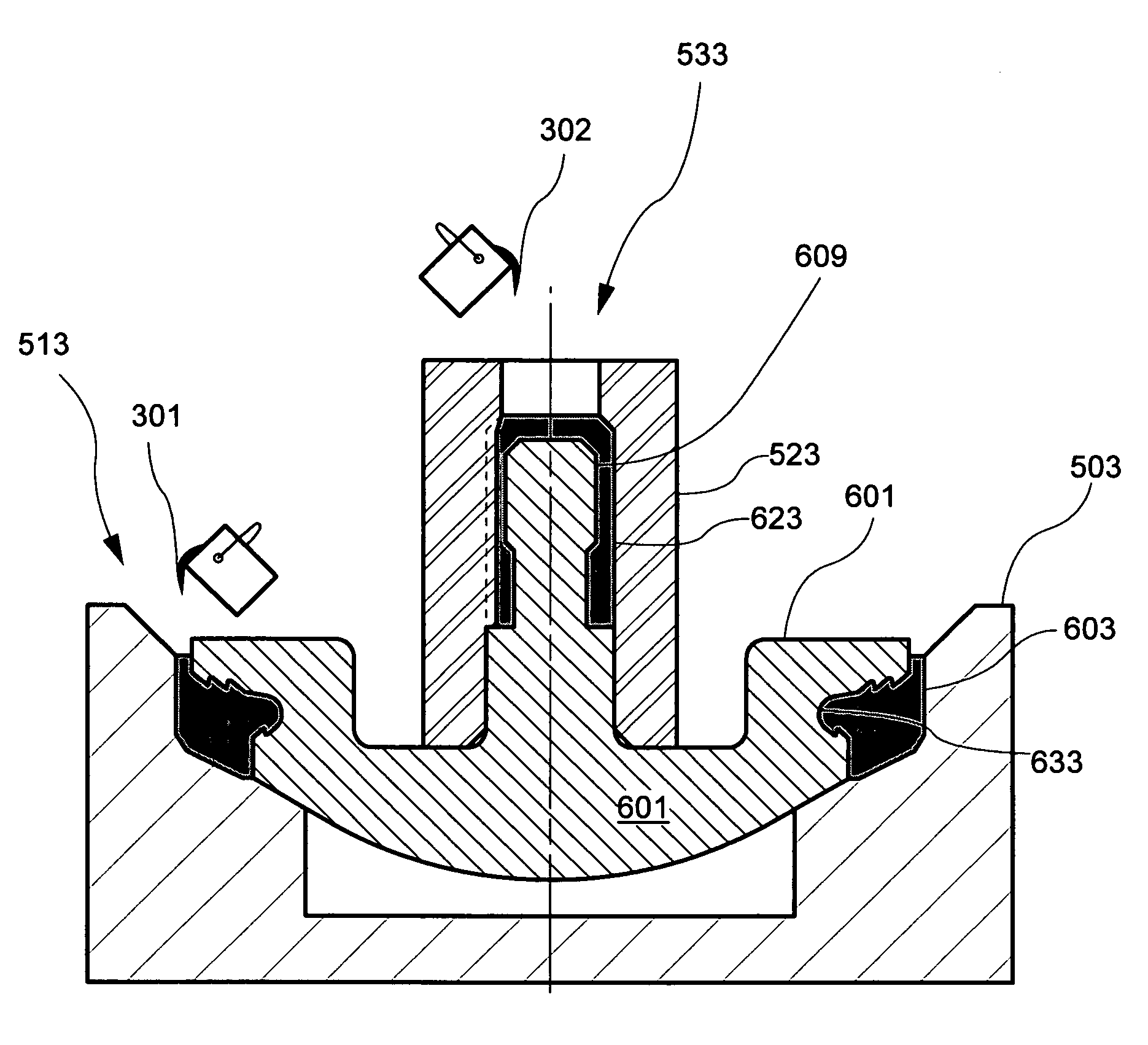
[0043]FIG. 9 schematically illustrates an embodiment of a valve body and seal assembly 699 comprising a top-stem-guided valve body 601 having a cast-in-place elastomeric seal insert 603 and a separate cast-in-place top guide stem sleeve 623 secured to valve body 601 according to a method of the present invention. Elastomeric seal insert 603 is cast-in-place in a peripheral seal retention groove 633 having first and second opposing groove sides 635 and 637 respectively, while guide stem sleeve 623 is cast-in-place on top guide stem 609. Note that the illustrated embodiment of top guide stem 609 comprises an undercut 643 having a chamfered superior wall 645 for further securing guide stem sleeve 623 to top guide stem 609 while allowing limited relative movement of guide stem sleeve 623 with respect to top guide stem 609. Guide stem sleeve 623 is additionally secured to top guide stem 609 by an ambient pressure greater than zero because the close fit of guide stem sleeve 623 on top gui...


PUM


Abstract

A valve body and seal assembly comprising a top-stem-guided valve body having at least one cast-in-place elastomeric seal insert in a peripheral seal retention groove and a cast-in-place top guide stem sleeve is made by pouring and curing liquid elastomer in at least one mold comprising the peripheral seal retention groove and the top guide stem. Mold surfaces contacting the poured elastomer are adhesion-inhibiting surfaces which reduce or eliminate background elastomer stress due to shrinkage during curing of the elastomer, and which allow limited relative movement of cast-in-place elastomer with respect to the valve body. Serrations on each of the opposing walls of the seal retention groove are offset to moderate differing stress concentrations in the groove walls.

Description

[0001]This is a continuation-in-part (CIP) patent application of U.S. Ser. No. 10 / 179,804 (hereinafter the '804 application), which was filed Jun. 25, 2002 now U.S. Pat. No. 6,955,181.FIELD OF THE INVENTION[0002]The present invention relates generally to valves suitable for rapid open-close cycling with abrasive fluids, such as drilling mud, under high pressures. More specifically, the invention relates to valves comprising a peripheral elastomeric seal and at least one elastomeric guide stem sheath on the moving element of the valve.BACKGROUND OF THE INVENTION[0003]Engineers typically design high-pressure oil field plunger pumps in two sections; the (proximal) power section and the (distal) fluid section. The power section usually comprises a crankshaft, reduction gears, bearings, connecting rods, crossheads, crosshead extension rods, etc. Commonly used fluid sections usually comprise a plunger pump housing having a suction valve in a suction bore, a discharge valve in a discharge ...

Claims


Application Information

Patent Timeline
IPC IPC(8): F16K15/06
CPCF04B53/102F04B53/1022F16K15/063Y10S137/902F05C2225/00Y10T137/7036Y10T137/0491Y10T137/7868
Inventor BLUME, GEORGE H.
Owner ALTIS INVESTMENTS LLC
Why Eureka
Try Eureka