Method and plant or increasing oil recovery by gas injection

a technology of gas injection and oil recovery, which is applied in the direction of liquefaction, lighting and heating equipment, borehole/well accessories, etc., can solve the problem of explosive gas formation, and achieve the effect of increasing oil recovery

Inactive Publication Date: 2007-01-30
DEN NORSKE STATS OLJESELSKAP AS
View PDF12 Cites 128 Cited by
  • Summary
  • Abstract
  • Description
  • Claims
  • Application Information

AI Technical Summary

Benefits of technology

[0017]injecting the nitrogen-rich fraction and at least a part of the waste gas into the oil reservoir to increase the oil recovery from the reservoir.
[0042]By combining a plant for production of high-purity nitrogen with the production of oxygen, the co-producing air separation unit only becomes 10–20% more expensive than an air separation unit that only produces high-purity nitrogen for injection into oil fields. This allows significant cost savings, both for production of synthesis products such as methanol and synthetic fuel, and for oil field injection.

Problems solved by technology

A too high ratio may lead to the formation of an explosive gas.

Method used


Image

  • Method and plant or increasing oil recovery by gas injection
  • Method and plant or increasing oil recovery by gas injection
  • Method and plant or increasing oil recovery by gas injection

Examples


example

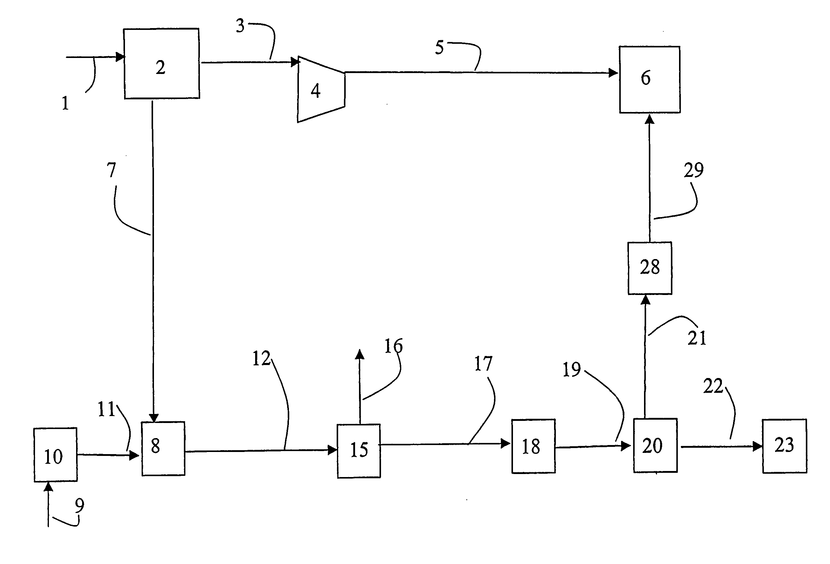
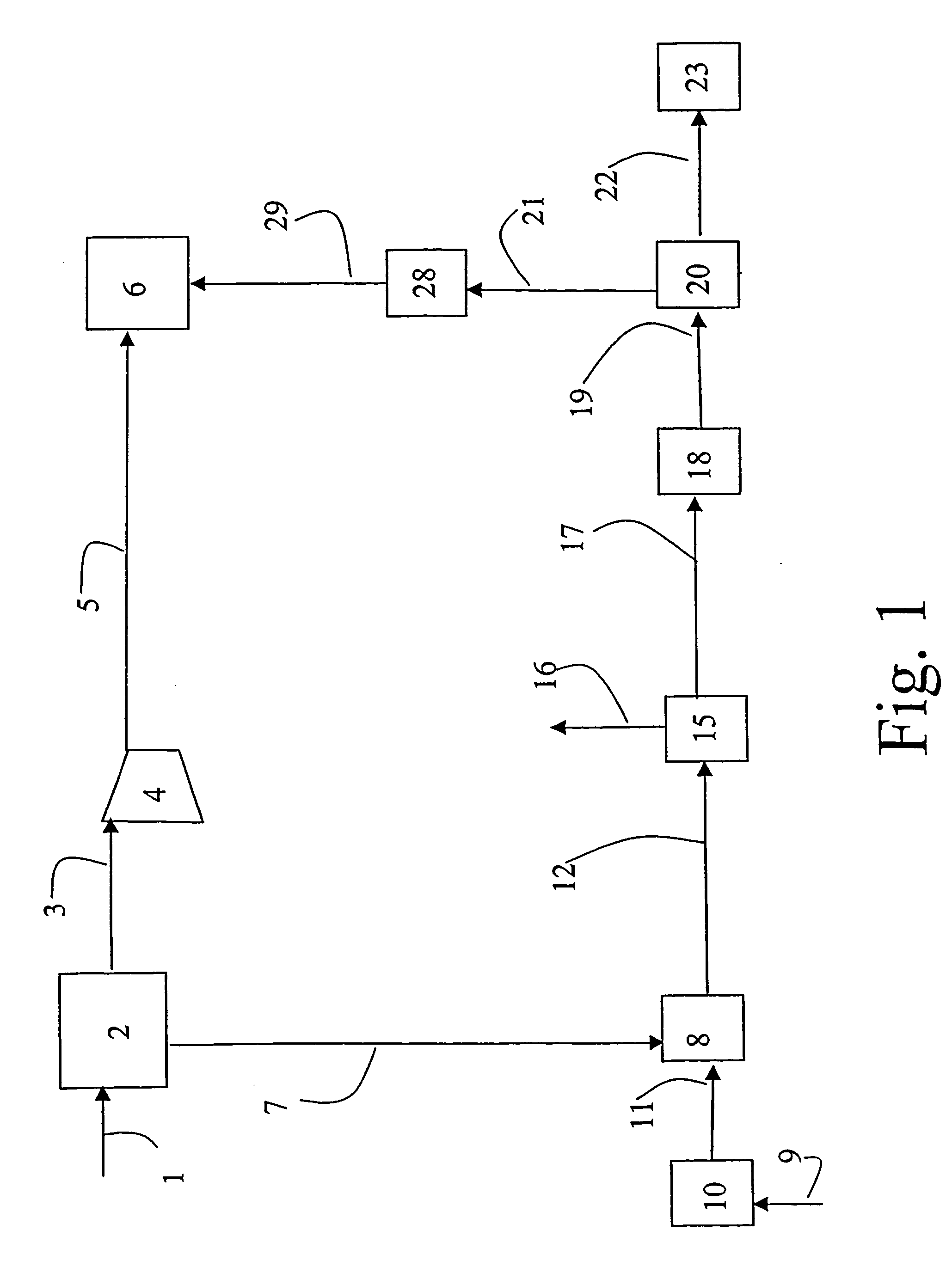
[0090]Calculations have been carried out for a plant according to FIG. 1 for production of methanol, which in addition comprises a bypass line that leads some of the synthesis gas in line 12 past the synthesis unit 15 and on to line 17.

[0091]The air separation unit can deliver 38 400 MTPD N2 and 6400 MUD O2. This air separation unit requires approximately 115 MW of power, which is delivered in the form of high pressure steam from the synthesis gas section.

[0092]The nitrogen is extracted at 3 bar and 0 degrees C. The gas is compressed to 220 bar for reinjection. Compression requires approximately 304 MW.

[0093]The oxygen can be fed to an autothermal reformer for production of synthesis gas from natural gas. The process operates with a steam / carbon ratio of 0.6. The temperature and pressure at the outlet from the ATR is 1030 degrees Celsius and 45 bar respectively. See Table 1 for the natural gas composition. Note, all compositions are given on a dry basis, i.e. without water.

[0094]

TAB...


PUM

PropertyMeasurementUnit
pressureaaaaaaaaaa
pressureaaaaaaaaaa
pressureaaaaaaaaaa

Abstract

A method and a plant for simultaneous production of a gas for injection into an oil field and production of methanol, dimethyl ether and / or other oxygenated hydrocarbons or production of higher hydrocarbons from natural gas is disclosed. An air separation unit (ATR) for production of pure nitrogen for injection and pure oxygen for production of synthesis gas (“syngas”) by authermal reformation of a natural gas is an essential part of the method and plant.

Description

CROSS REFERENCE TO RELATED APPLICATIONS[0001]This application is based on International Application No. PCT / NO02 / 00305, filed 30 Aug. 2002, having an International Publication Number of WO 03 / 018959 A1 and an International Publication Date of 6 Mar. 2003, which is based on International Application No. PCT / NO01 / 00356, filed 31 Aug. 2001.THE FIELD OF THE INVENTION[0002]The present invention regards the use of natural gas in the development of industry and oil fields. In particular, the invention regards a method and a plant for integrated production of synthesis gas and gas for injection into an oil reservoir.THE BACKGROUND OF THE INVENTION[0003]The reinjection of various gases into an oil reservoir in order to enhance the oil recovery from the reservoir, and to stabilize it, has long been known and used. Gases such as CO2, N2 and natural gas will reduce the surface tension between gas and oil, and thus contribute to both increased recovery and stabilization of the reservoir.[0004]Na...

Claims


Application Information

Patent Timeline
Patent Type & Authority Patents(United States)
IPC IPC(8): E21B43/18E21B43/34C01B3/34C07C29/151C10G2/00E21B43/16F25J3/04
CPCC01B3/34C07C29/1518C10G2/30E21B43/168F25J3/04593F25J3/04533F25J3/04539F25J3/04569F25J3/04575C07C31/04C01B2203/0205C01B2203/0244C01B2203/0283
Inventor OLSVIK, OLARYTTER, ERLINGSOGGE, JOSTEINKVALE, RUNEHAUGEN, SJURGRONTVEDT, JAN
Owner DEN NORSKE STATS OLJESELSKAP AS
Why Eureka
Try Eureka