Rapid exchange sheath for deployment of medical devices and methods of use

a technology of medical devices and sheaths, applied in the field of surgical devices and methods for deploying endoluminal medical devices, can solve the problems of ischemia or infarct of the organ which the vessel supplies, occlusion of the narrower vessels downstream, and possible stroke causes, and the inability to adjust the steerability of the guidewir

Inactive Publication Date: 2007-01-30
BOSTON SCI SCIMED INC
View PDF243 Cites 217 Cited by
  • Summary
  • Abstract
  • Description
  • Claims
  • Application Information

AI Technical Summary

Benefits of technology

[0010]In another embodiment, the rapid exchange sheath comprises an elongate member which includes a third opening a short distance proximal the first opening. The guidewire is passed through the first and second openings, and the support wire is passed through the first and third openings. In certain embodiments, the elongate member has a lumen which communicates with the proximal and distal ends and is adapted for infusion and aspiration of fluid or blood. In certain embodiments, the proximal end of the tubular member includes a hemostatic valve for preventing back flow of blood during insertion into a vessel.
[0011]The methods of the present invention are useful for deploying a medical device within a body cavity and for protecting a patient from embolization during an endovascular procedure. The rapid exchange sheaths can be inserted to deploy medical instruments within the coronary artery, aorta, common carotid artery, external and internal carotid arteries, brachiocephalic trunk, middle cerebral artery, basilar artery, subclavian artery, brachial artery, axillary artery, iliac artery, renal artery, femoral artery, popliteal artery, celiac artery, superior mesenteric artery, inferior mesenteric artery, anterior tibial artery, posterior tibial artery, and all other arteries carrying oxygenated blood. The sheaths can be used prophylactically in patients with hypercoagulable state, including protein C or protein S deficiency, to deploy a filter and prevent pulmonary embolism. It can also be used during an endovascular procedure to gain access and to prevent distal embolization of thrombi and / or foreign bodies in the venous circulation, including the superior vena cava, inferior vena cava, external and internal jugular veins, brachiocephalic vein, pulmonary artery, subclavian vein, brachial vein, axillary vein, iliac vein, renal vein, femoral vein, profunda femoris vein, great saphenous vein, portal vein, splenic vein, hepatic vein, and azygous vein.
[0015]It will be understood that there are several advantages in using the rapid exchange sheaths and methods disclosed herein for deployment of medical devices during endovascular procedures. For example, the sheaths (1) provide access over a guidewire to a region of interest within a vessel, (2) allow deployment of a selected endoluminal medical device to a region of interest while safely carried within the sheath, (3) allow removal of the guidewire once the sheath and first endoluminal device are in place, (4) provide for removal of the sheath while avoiding the use of an extended segment of guidewire outside the patient's body, (5) allow use of a support wire as the first endoluminal device to provide distal embolic protection, (6) protect the support wire carrying the filter during its insertion, thereby minimizing bending, kinking, and / or looping around in the vessel, and (7) can be used in adult and pediatric patients.

Problems solved by technology

It is well recognized that one of the complications associated with endovascular techniques is the dislodgment of embolic materials generated during manipulation of the vessel, thereby causing occlusion of the narrower vessels downstream and ischemia or infarct of the organ which the vessel supplies.
Microemboli, as detected by transcranial Doppler monitoring in this study, have been shown to be a potential cause of stroke.
However, one major disadvantage associated with the current devices is that the steerability of the guidewire may be altered as compared to the conventional guidewires due to the size of the filter.
The guidewire may bend, kink, and / or loop around in the vessel, making insertion of the filter through a complex vascular lesion difficult.
However, the guidewire position is often lost or compromised during the exchange of devices.
It is known that there are few interventional maneuvers as challenging as attempting to maintain distal guidewire access while trying to exchange one guiding catheter for another without compromising the guidewire position.
Existing devices are inadequate for this purpose.

Method used


Image

  • Rapid exchange sheath for deployment of medical devices and methods of use
  • Rapid exchange sheath for deployment of medical devices and methods of use
  • Rapid exchange sheath for deployment of medical devices and methods of use

Examples


Embodiment Construction

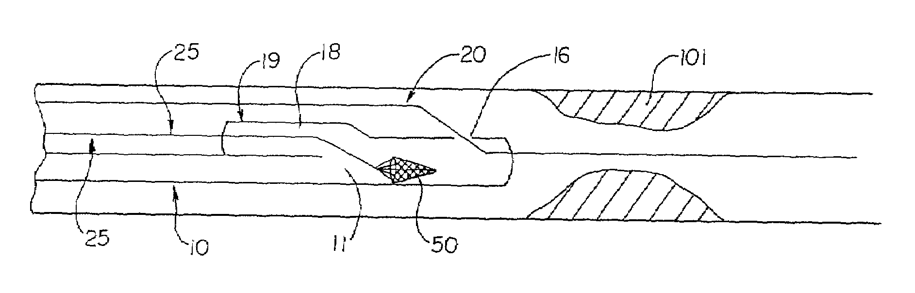
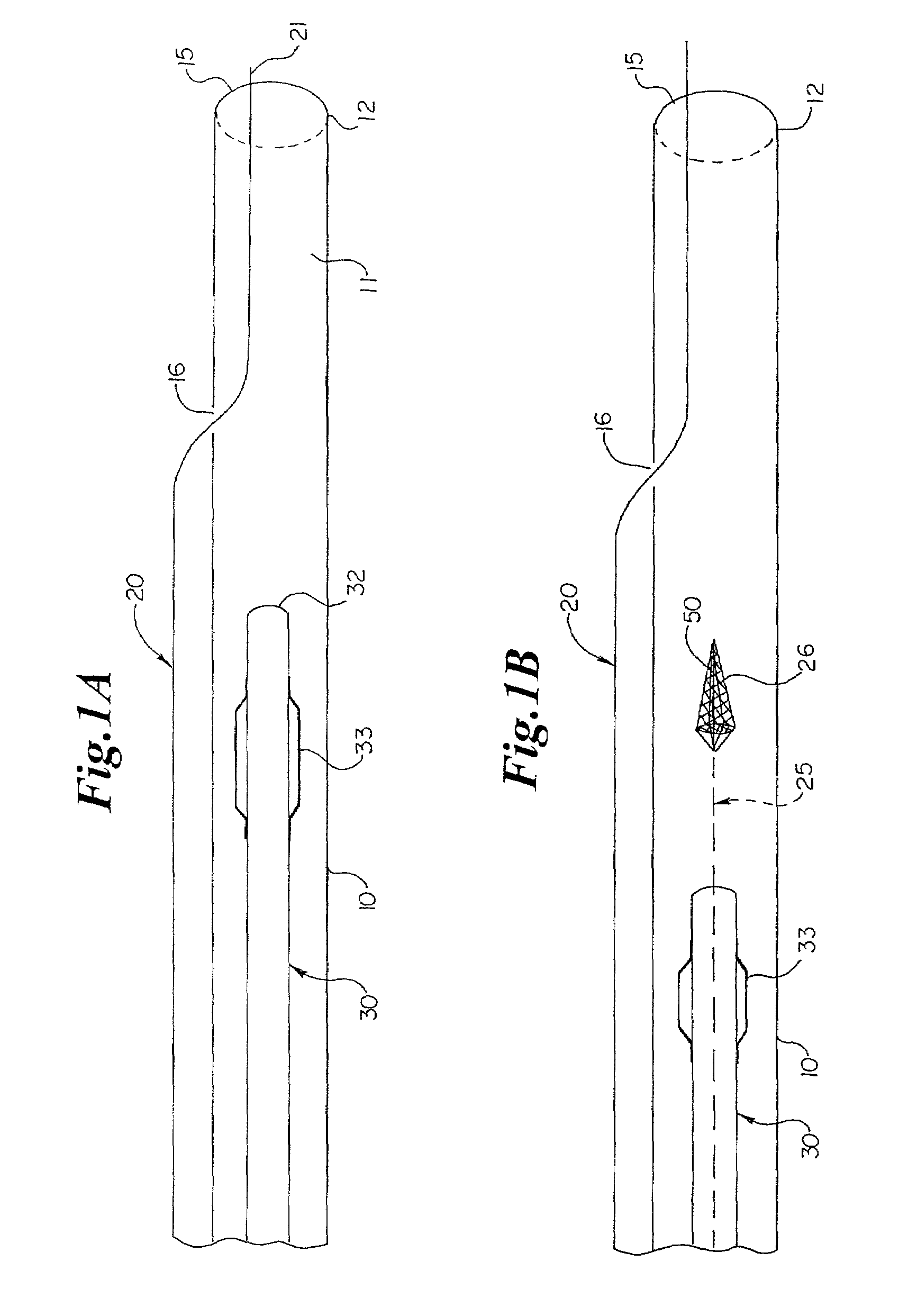
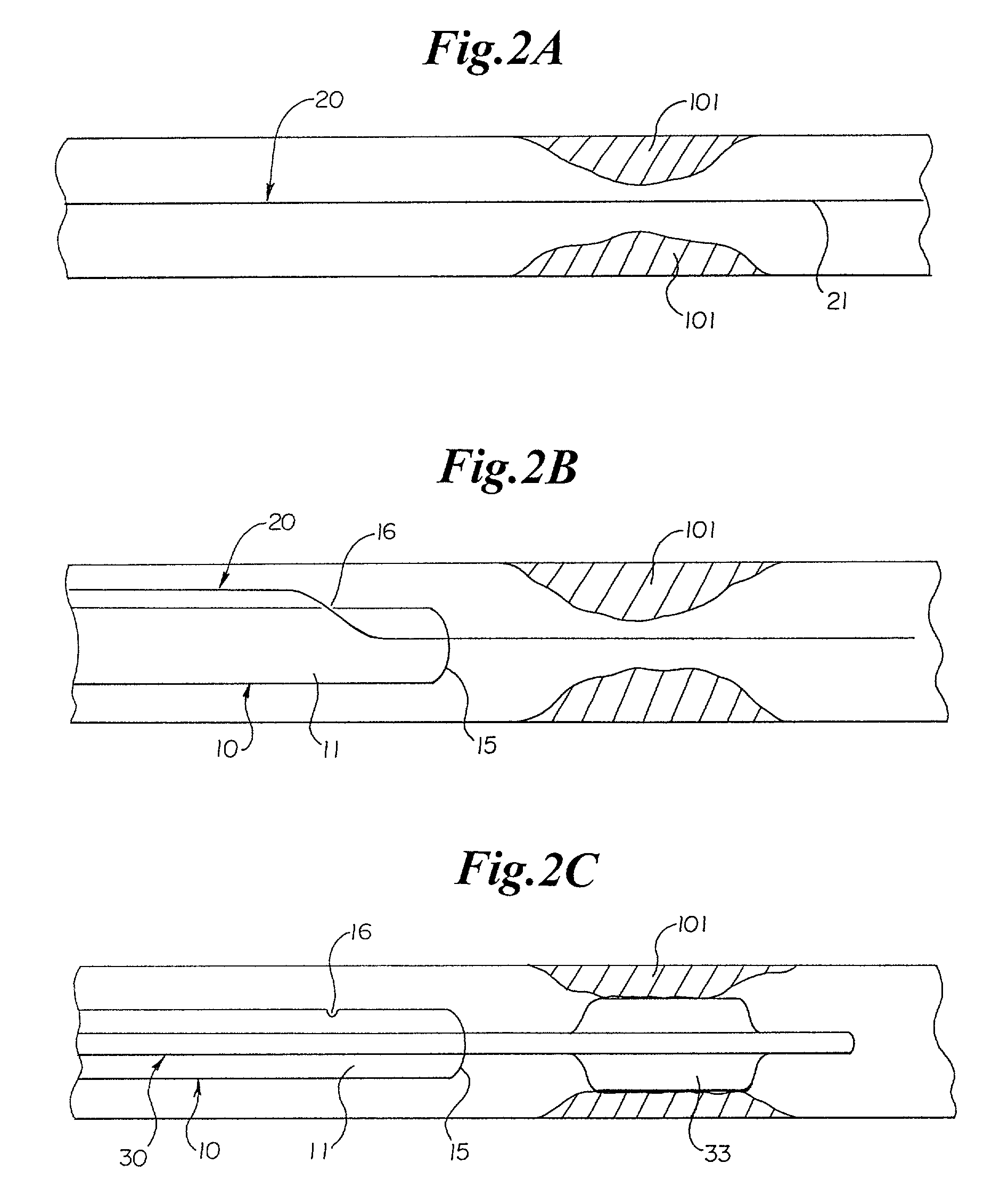
[0042]Referring now to the drawings, an embodiment of the rapid exchange sheath for deployment of angioplasty catheter 30 is depicted in FIG. 1A. The sheath comprises elongate tubular member 10 having lumen 11 communicating with a proximal end and distal end 12. Tubular member 10 has first opening 15 at distal end 12, and second opening 16 a short distance proximal to distal end 12. Opening 16 can be located from 1 millimeter to 50 centimeters proximal of openings 15, and at distances of 2, 4, 6, 8, 10, 12, 14, 16, or 18 centimeters proximal of opening 15, or at any other suitable distance. Lumen 11 is adapted to receive an endoluminal medical device, such as angioplasty catheter 30. Angioplasty balloon 33 is mounted on distal end 32 of the angioplasty catheter. Guidewire 20, which has a proximal end and distal end 21, passes through opening 16, lumen 11, and opening 15 of tubular member 10.

[0043]Another embodiment of the rapid exchange sheath for deployment of angioplasty catheter ...


PUM


Abstract

A rapid exchange sheath comprising an elongate tubular member, a guidewire, and support wire having an expandable filter at a distal end. The guidewire passes through a first opening at a distal end of the tubular member and a second opening a short distance proximal from the distal end. The support wire is received in a lumen of the tubular member, or, in certain embodiments, extends proximally through a third opening a short distance proximal from the distal end. Methods of using the sheaths for deploying and / or exchanging medical device(s) in a patient's vessel are also disclosed.

Description

[0001]This application hereby claims the benefit under Title 35, United States Code, §119(e) of U.S. Provisional Application Ser. No. 60 / 262,136 filed on Jan. 16, 2001.FIELD OF THE INVENTION[0002]The present invention relates generally to devices and methods for deploying an endoluminal medical device, e.g., an angioplasty, atherectomy, or stent deployment catheter, to a region of interest within the vessel. More particularly, the invention provides a rapid exchange sheath for deployment of medical devices for directing and / or exchanging “over the wire” medical devices.BACKGROUND OF THE INVENTION[0003]Treatment of thrombotic or atherosclerotic lesions in blood vessels using an endovascular approach has recently proven to be an effective and reliable alternative to surgical intervention in selected patients. For example, directional atherectomy and percutaneous translumenal coronary angioplasty (PTCA) with or without stent deployment are useful in treating patients with coronary occl...

Claims


Application Information

Patent Timeline
Patent Type & Authority Patents(United States)
IPC IPC(8): A61M29/00A61B17/00A61B17/22A61F2/01A61F2/84A61M25/00A61M25/01A61M25/06A61M29/02
CPCA61B17/221A61F2/013A61M25/0169A61M25/0172A61M25/0662A61F2/958A61F2230/0093A61M2025/018A61M2025/0183A61F2002/018A61F2230/0006A61F2230/0067A61M25/104
Inventor BELEF, W. MARTINTSUGITA, ROSS S.
Owner BOSTON SCI SCIMED INC
Why Eureka
Try Eureka