Vertebral implant for promoting arthrodesis of the spine

a technology of vertebral implants and arthrodesis, which is applied in the field of intervertebral implants, can solve the problems of inability to maintain the desired disc space, inconvenient manipulation of hand tools, and inability to strengthen and integrity of the endplate, and achieves the effects of enhancing access to the implant cavity, preventing sliding of hand tools, and being easily manipulated

Inactive Publication Date: 2007-01-30
WARSAW ORTHOPEDIC INC
View PDF69 Cites 169 Cited by
  • Summary
  • Abstract
  • Description
  • Claims
  • Application Information

AI Technical Summary

Benefits of technology

[0056]In order to prevent a sliding of the hand tool off the implant, the receiving means on the rear wall is advantageously formed such that it also serves as a holding means. The hand tool, can for instance, be provided with a clamp, by means of which the implant can be held tight, e.g. by engagement into the grooves, so that the implant is connected with the hand tool as a joined unit and can be readily manipulated by the surgeon to precisely place the implant in the desired position in the disc space. In order to determine the position of the implant with respect to the hand tool even more precisely, the opening in the implant can extend through the rear wall and aligned with a second through hole formed through the opposite frontal wall on the opposite end of the implant. A corresponding pin or shaft on the hand tool can be extended through the first through hole and into the second though hole thereby centering the implant on the hand tool. The frontal side through hole enhances access to the implant cavity to facilitate ingrowth of tissue into the implant from its front side.

Problems solved by technology

The strength and integrity of the endplate may be compromised.
This results in a failure to maintain the desired disc space height and causes tremendous pain to the patient.
Titanium and surgical steel provide the requisite strength to maintain correct disc space height and orientation; however, some evidence exists that these materials may stress shield the bone.
However, suitable donor bone is scarce.

Method used


Image

  • Vertebral implant for promoting arthrodesis of the spine
  • Vertebral implant for promoting arthrodesis of the spine
  • Vertebral implant for promoting arthrodesis of the spine

Examples


Embodiment Construction

[0073]For the purposes of promoting an understanding of the principles of the invention, reference will now be made to the embodiments illustrated herein and specific language will be used to describe the same. It will nevertheless be understood that no limitation of the scope of the invention is thereby intended. Any alterations and further modifications in the described processes, systems or devices, and any further applications of the principles of the invention as described herein, are contemplated as would normally occur to one skilled in the art to which the invention relates.

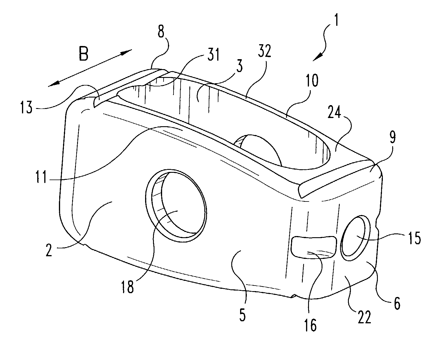
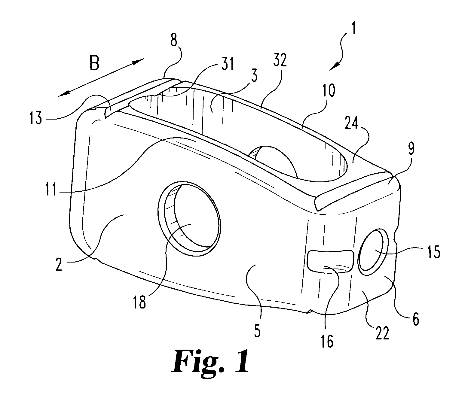
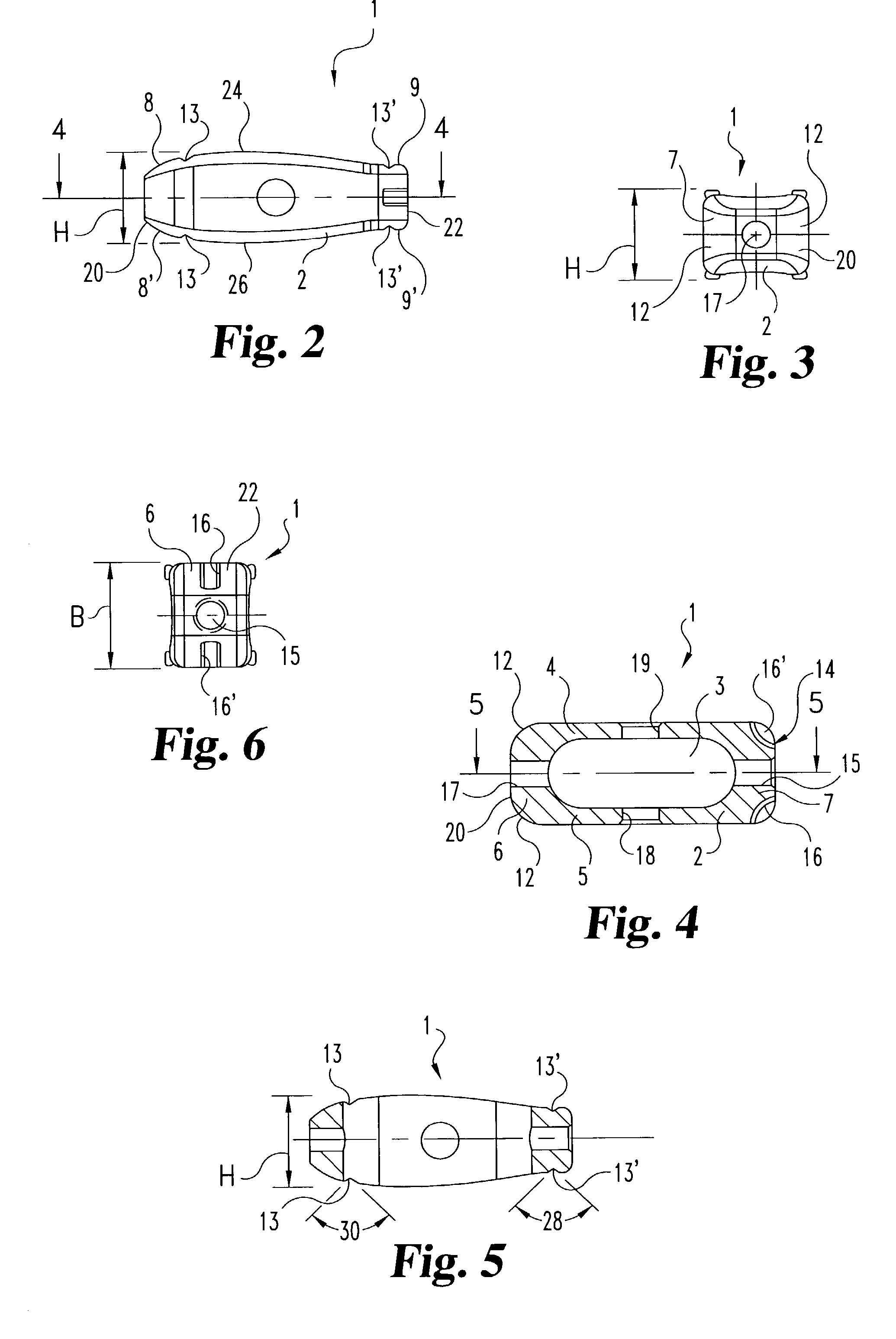
[0074]FIGS. 1–5 illustrate intervertebral implant 1 according to the present invention. Implant 1 is formed by an elongated basis body 2 defining a longitudinal axis. Cavity 3 is formed in body 2. Cavity 3 is surrounded by two longitudinal walls 4, 5 and two endwalls 6, 7 (rear wall 6 and a front wall 7). Cavity 3 is formed to extend through in the height direction H of the body 2 and is provided to have ...


PUM


Abstract

This invention provides a vertebral implant for impaction in a disc space to restore and/or maintain desired disc space height and spinal orientation. The implant has an elongated basis body having a generally lens-shape provided by convex upper and lower surfaces. Bearing surfaces are provided on the cross-edge surfaces of the endwalls. Grooves are provided in the upper and lower surfaces positioned between the bearing surfaces. The implant can be prepared from a wide variety of materials including metallic materials, synthetic materials, polymeric materials, ceramic materials, and composite materials including reinforced materials i.e. glass, fiber, and/or carbon fiber reinforced materials (CFRP). These preferred materials for fabricating implants in the present invention reduce costs, increase service life and provide excellent physiological compatibility. The non-metallic material can be selected to be either a substantially permanent material, a biodegradable material or a bioerodable material. Further, the implant material can be provided to be radio opaque to facilitate monitoring of bone ingrowth both into the implant and between the opposing endplates of the adjacent vertebrae.

Description

CROSS-REFERENCE TO RELATED APPLICATIONS[0001]The present application claims the benefit of German Utility Model Application 200 04 693.4, filed on Mar. 14, 2000, and PCT Application No. U.S. / 01 / 08073 filed on Mar. 14, 2001, which are hereby incorporated by reference in their entirety.TECHNICAL FIELD[0002]This invention relates to an intervertebral implant for treatment of spinal deformities. More preferably, this invention is directed to a metallic or synthetic, intervertebral implant for implantation into a prepared disc space to facilitate spinal fusion, maintain desired disc space height, and / or spinal orientation.BACKGROUND[0003]For degenerated, diseased or otherwise damaged spinal columns and vertebrae, it is known to treat these defects by removal of all or a portion of the vertebral disc and inserting an implant such as a spinal implant to restore normal disc height and spine orientation, and repair the spinal defects. When desired, osteogenic material also can be implanted i...

Claims


Application Information

Patent Timeline
Patent Type & Authority Patents(United States)
IPC IPC(8): A61F2/44A61F2/00A61F2/28A61F2/30A61F2/46
CPCA61F2/447A61F2/30965A61F2/442A61F2/4611A61F2002/2835A61F2002/3008A61F2250/0098A61F2002/30774A61F2002/30785A61F2002/30789A61F2002/4475A61F2230/0082A61F2002/30271A61F2002/30261A61F2002/30593
Inventor LIU, MINGYANFRUH, HANS-JOACHIMEBNER, HARALDESTES, BRADLEY T.
Owner WARSAW ORTHOPEDIC INC
Why Eureka
Try Eureka