
Emitter with dielectric layer having implanted conducting centers

a dielectric layer and emitter technology, applied in the field of microelectronics, can solve the problems of general cost and time consumption, unstable tip, and high cost of a transmitter

Active Publication Date: 2007-01-30
SAMSUNG ELECTRONICS CO LTD
View PDF29 Cites 11 Cited by
  • Summary
  • Abstract
  • Description
  • Claims
  • Application Information

AI Technical Summary

Problems solved by technology

Manufacturing of spindt tip emitters requires a number of relatively difficult deposition steps, with the result that it is generally expensive and time consuming.
Once formed, a tip may be unstable as it can change as it is operated, and is subject to damage if not operated in high vacuum.

Method used


Image

  • Emitter with dielectric layer having implanted conducting centers
  • Emitter with dielectric layer having implanted conducting centers
  • Emitter with dielectric layer having implanted conducting centers

Examples


Embodiment Construction

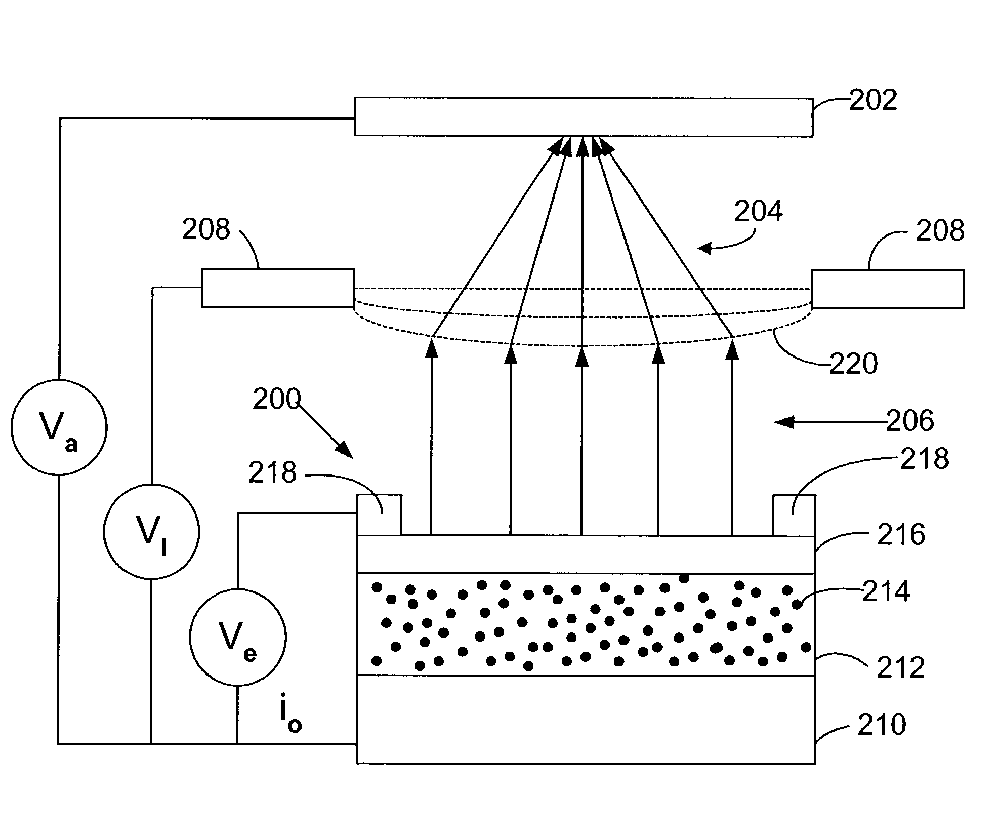
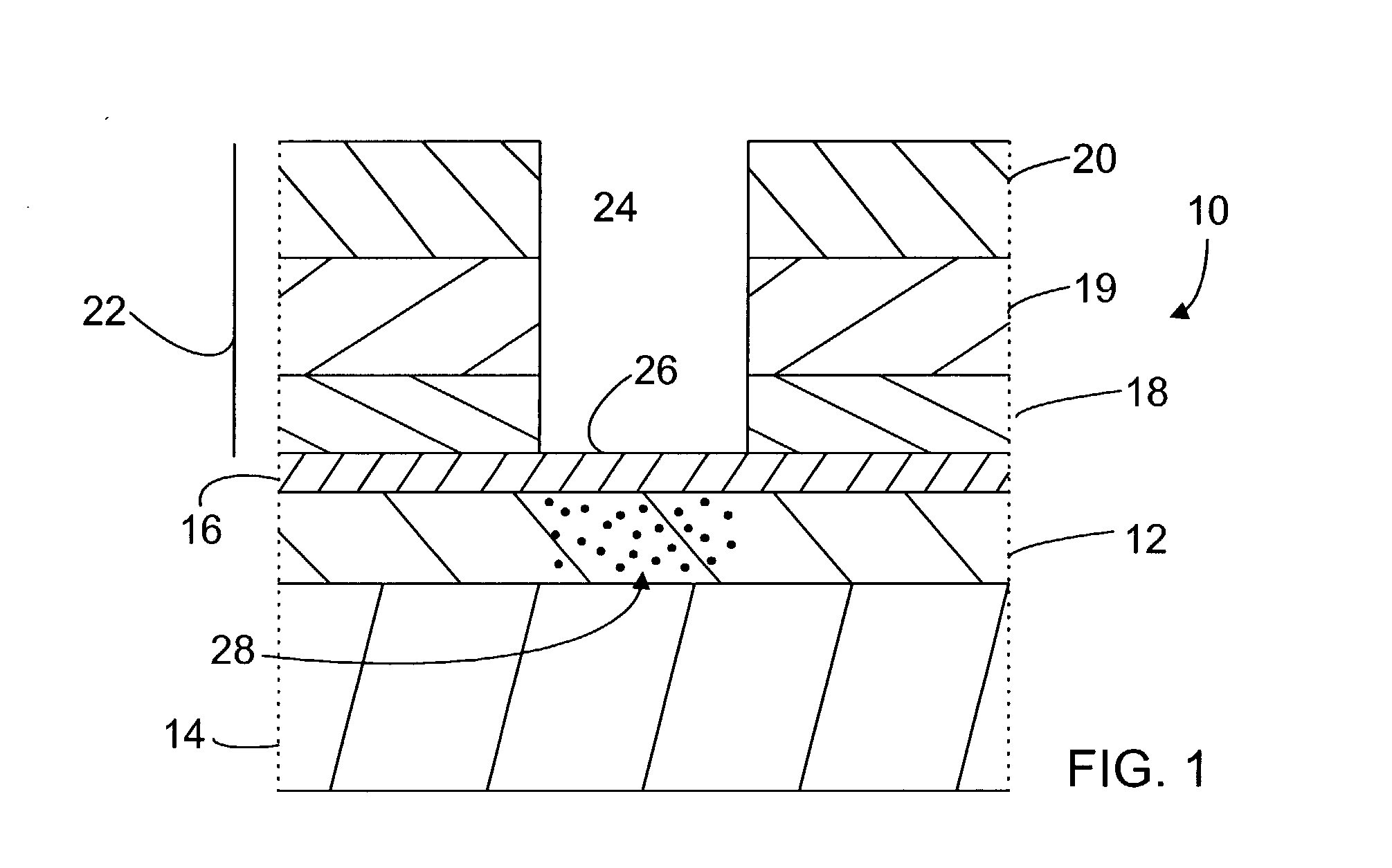
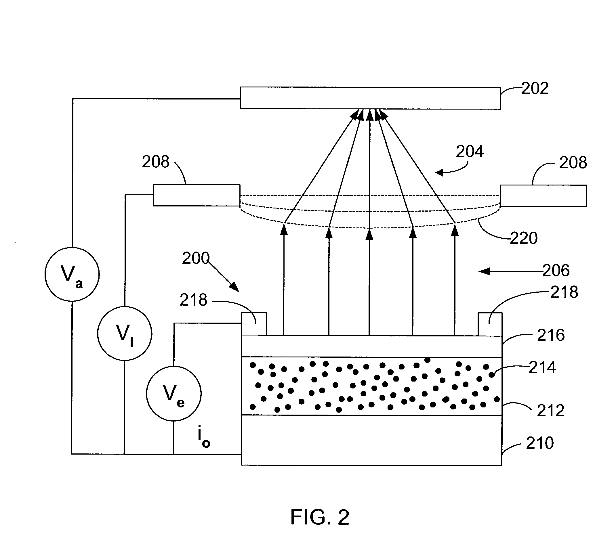
[0012]The present invention concerns an emitter having a dielectric layer deposited on an electron supply layer, with a thin metal layer deposited on the dielectric layer. The dielectric layer has a plurality of conducting centers therein, which preferably comprise implanted metal ions. The conducting centers may facilitate travel of electrons through the dielectric by quantum tunneling. Other invention embodiments may be directed to devices incorporating an emitter, with examples including an integrated circuit, a display device, and a memory device.

[0013]Turning now to the drawings, a preferred embodiment emitter 10 of the invention is shown in cross section in FIG. 1. A dielectric layer 12 is formed on an electron source layer 14. The dielectric layer 12 preferably comprises a nitride or an oxide of transition metals. Preferred materials include nitrides and oxides of Si or Ti For example, the dielectric layer 12 may comprise a material of the formula AOx where A is one of Si or ...


PUM

PropertyMeasurementUnit
diameteraaaaaaaaaa
thicknessaaaaaaaaaa
thicknessaaaaaaaaaa

Abstract

An emitter has a dielectric layer formed on a conductor, with a thin metal layer over the dielectric. A plurality of conducting centers is in the dielectric layer to allow electrons to pass through the dielectric from the conductor to the thin metal layer via quantum tunneling.

Description

FIELD OF THE INVENTION[0001]The invention is in the microelectronics field. The invention particularly concerns emitters and devices incorporating emitters.BACKGROUND OF THE INVENTION[0002]Emitters have a wide range of potential applicability in the microelectronics field. An emitter emits electrons in response to an electrical signal. The controlled emissions form a basis to create a range of useful electrical and optical effects. Prior conventional emitters include spindt tip cold cathode devices.[0003]Challenges presented by spindt tip emitters include their manufacturability and stability over their service life. Manufacturing of spindt tip emitters requires a number of relatively difficult deposition steps, with the result that it is generally expensive and time consuming. Once formed, a tip may be unstable as it can change as it is operated, and is subject to damage if not operated in high vacuum.[0004]Traditional flat emitters are comparably advantageous because they present ...

Claims


Application Information

Patent Timeline
Patent Type & Authority Patents(United States)
IPC IPC(8): H01J1/62H01J1/312H01J9/02H01J19/24H01J21/14H01J29/04H01J31/12
CPCB82Y10/00H01J9/027H01J1/312
Inventor SMITH, JAMES DENNINGBENNING, PAUL
Owner SAMSUNG ELECTRONICS CO LTD
Learn More