Antenna couplers and method of production

a technology of antenna couplers and couplers, applied in the field of antenna couplers, can solve the problems of bulky test equipment, difficult to reach conveniently, and relatively expensive and bulky test equipment, and achieve the effects of reducing the size, complexity and cost of antenna couplers, and low cos

Inactive Publication Date: 2007-01-30
BAE SYST INFORMATION & ELECTRONICS SYST INTEGRATION INC
View PDF6 Cites 5 Cited by
  • Summary
  • Abstract
  • Description
  • Claims
  • Application Information

AI Technical Summary

Benefits of technology

[0008]The present invention is a low cost, compact size antenna coupler and a method for its production and use, which is based on reducing the size, complexity and cost of antenna couplers by employing a novel near-field sensing probe in place of the usual coupler antenna element. All currently deployed U.S. Air Force antenna couplers utilize commercially produced antennas as the coupling elements. A 2.5″ broadband (2 to 18 GHz) Cavity Backed Spiral, similar to the antennas used for RWR quadrant receivers, is most commonly used. These antennas are well behaved over broad frequency ranges, are compact, and are widely available. A 2.5″ Cavity Backed Spiral (AS-218 series, ≈2–8 GHz BW) built by BAE SYSTEMS Information and Electronic Systems Integration Inc. (IEWS) is widely used in BAE SYSTEMS IEWS designs as well as a smaller BAE SYSTEMS IEWS built 1.0″ variant (AS-83 series, ≈6–16 GHz BW). Virtually all BAE SYSTEMS IEWS built Antenna Couplers use either an AS-218 or AS-83 series antenna.
[0009]One aspect of the present invention is to provide a quick check conformal antenna coupler which provides reliable, repeatable RF interfacing, a smaller footprint than traditional prior art couplers, and avoids the need to remove the aircraft radomes when performing tests on the enclosed radar.
[0011]A further aspect is to provide such a coupler which is formed of lightweight, durable fiberglass material, which is constructed to conform to the unique aircraft and radome profile on which it will be utilized, and which provides electromagnetic interference / electromagnetic compatibility (EMI / EMC) shielding and effective bandwidth.
[0012]Another aspect of the invention is that the antenna coupler can be mounted easily on an aircraft with or without auxiliary hardware or can be manually held in position while performing tests thereon.
[0013]The invention provides such an antenna coupler which can be a consumable end item, that is, it can be replaced due to its low cost and not repaired if damaged. This also avoids the need to store numerous repair parts, especially where space is at a premium, such as aboard a ship. Also it requires no complicated logistics to utilize the same.

Problems solved by technology

Also each aircraft generally will have a number of radar antennas protected by radomes, each of which heretofore had to be removed in order to perform the required tests requiring the use of relatively expensive and bulky test equipment.
Also the locations of the radar antennas vary and are at locations, sometimes difficult to reach conveniently with such prior art heavy and bulky test equipment.
Because of these design constraints existing antenna couplers are high cost items.
Thus, antenna couplers for these applications tend to be rather large, expensive to use and maintain, and bulky to transport and store.

Method used


Image

  • Antenna couplers and method of production
  • Antenna couplers and method of production
  • Antenna couplers and method of production

Examples


second embodiment

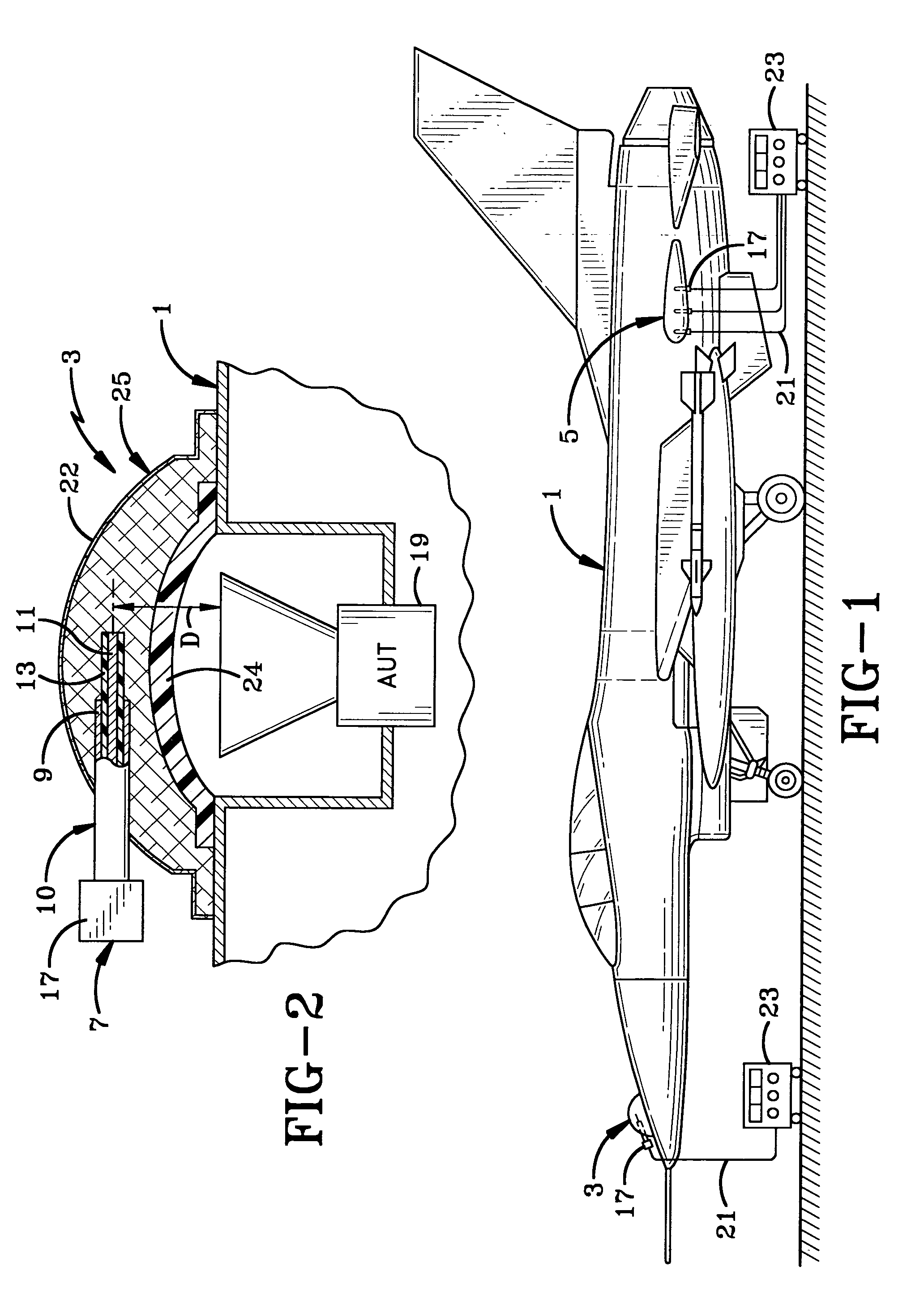
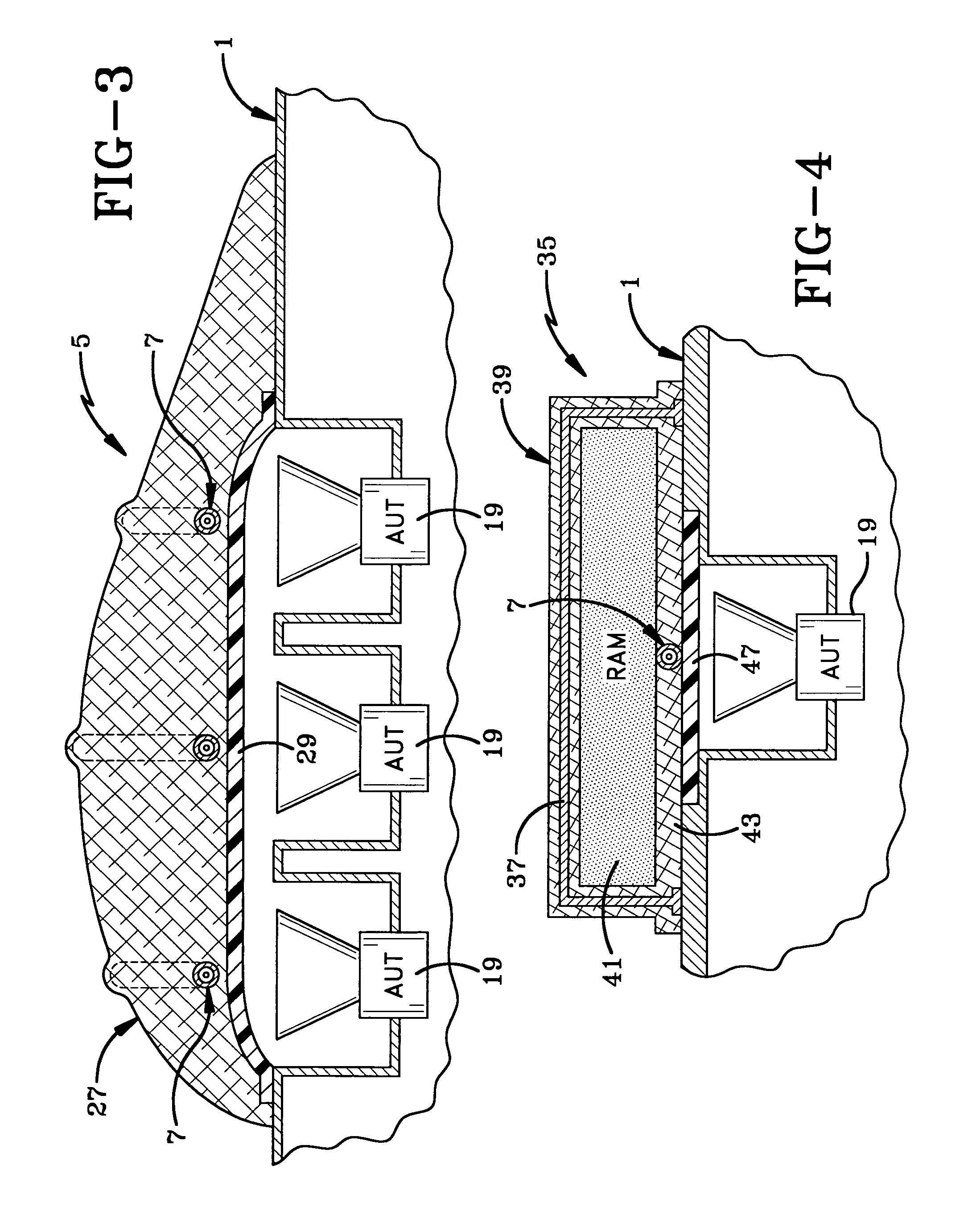
[0025]the antenna coupler indicated at 5, is shown in detail in FIG. 3, and is similar in most respects to coupler 3 discussed above except that it includes a plurality or an array of individual probes 7 spaced from each other throughout a coupler shell 27. Shell 27 also is fabricated from laid-up sheets of fiberglass shaped so that it conforms to the shape of the aircraft, and in particular to the radome 29 thereof, so that probes 7 formed from coaxial cables 10, are located at the required distances from the apertures of the multiple AUT 19. Each of the coaxial cables 10 embedded in shell 27 have an RF connector 17 at the exposed ends thereof for connection to test equipment 23 as shown in FIG. 1.

third embodiment

[0026]A third embodiment is indicated generally at 35 (FIG. 4), and is similar to embodiments 3 and 5 discussed above with the exception that it includes a metallic screen 37 embedded within a dielectric shell 39 where it is separated from probe 7 by a layer of radar absorbent material (RAM) indicated at 41. Probe 7 will be embedded within an innermost layer 43 of the fiberglass so as to be at the correct spacing from the aperture of an AUT 19. Again, as shown in FIG. 4, dielectric shell 39 is placed over an aircraft radome 47 eliminating the need for removal of the same as required in prior tests. Also, a gel-coat layer (not shown) may be placed over the layers of fiberglass in forming the finalized dielectric shell 39.

[0027]As discussed above, probe 7 shown in the various embodiments will have an exposed center conductor equal to or less than ¼ wavelength at the low end of the operating frequency range of the aperture of the AUT. As examples, a 500 MHz antenna signal will have a ¼...


PUM


Abstract

A method of producing an antenna coupler for placement on an antenna under test (AUT) having an aperture. This method includes the steps of constructing a probe from a section of RF hard-line stock having a center conductor and an outer conductor. The outer conductor is removed to expose a portion of the center conductor having a length equal to or less than ¼ wavelength of the AUT. The probe is embedded within a fiberglass shell and has an exposed RF connector for connection to equipment for performing tests on the AUT. The probe is then positioned across the aperture of the Antenna Under Test (AUT).

Description

BACKGROUND OF THE INVENTION[0001]This application is a 371 of PCT / US04 / 40032 filed on Nov. 29, 2004.[0002]1. Technical Field[0003]The present invention relates to antennas and more particularly to antenna couplers. Even more particularly, the invention relates to a quick check conformal antenna coupler which provides a reliable and repeatable RF interface between aircraft electronic countermeasure (ECM) system installations and flightline automated test equipment (ATE) without requiring the removal of aircraft radomes.[0004]2. Background Information[0005]Antenna couplers are devices used to match the impedance of a transmitter and / or receiver to an antenna to provide maximum power transfer. One of their uses is to provide the RF interface between an aircraft electronic countermeasure system (ECM) installation and flightline Automatic Test Equipment (ATE). Unlike most radar and communications systems, ECM systems typically operate over a wide range of frequencies, an octave or more i...

Claims


Application Information

Patent Timeline
Patent Type & Authority Patents(United States)
IPC IPC(8): G01R29/10H01Q1/50
CPCH01Q1/50H01Q1/28G01R29/10
Inventor TOWN, GRAHAM D.
Owner BAE SYST INFORMATION & ELECTRONICS SYST INTEGRATION INC
Why Eureka
Try Eureka