Computer-assisted-design of piping swing-joint intersections

a computer-aided design and swing-joint intersection technology, applied in electrical/magnetic computing, instruments, analogue processes for specific applications, etc., can solve the problems of difficult manual calculation of swing-joint intersections, a great deal of designer's time and effort,

Active Publication Date: 2007-01-30
M E P CAD
View PDF11 Cites 11 Cited by
  • Summary
  • Abstract
  • Description
  • Claims
  • Application Information

AI Technical Summary

Benefits of technology

[0009]A primary object of this invention is to provide a method and apparatus for assisting layout design which readily

Problems solved by technology

As a result, it takes a great deal of the designer's time and effort to create swing-joint intersections in the design layout.
Swing-joint intersections are particularly difficult to calculate manually because pipe layout object segments must be modified to arrive at that point, in three dime

Method used


Image

  • Computer-assisted-design of piping swing-joint intersections
  • Computer-assisted-design of piping swing-joint intersections
  • Computer-assisted-design of piping swing-joint intersections

Examples


Embodiment Construction

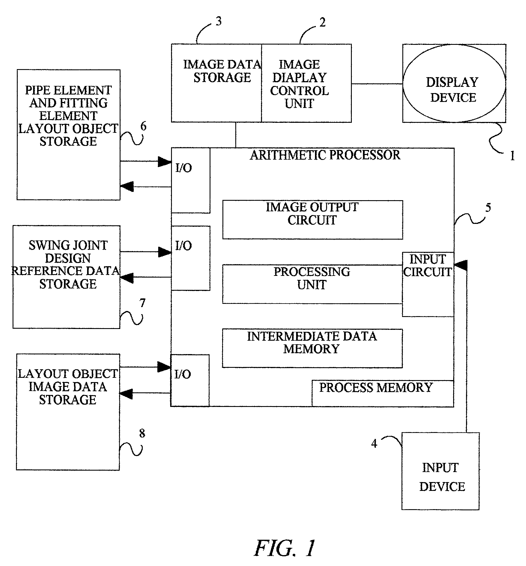
[0026]The computer architecture and associated hardware for designing swing-joint interconnections in a CAD system of piping is well known, and many suitable computer and hardware combinations may be programmed to complete the system according to the present invention. Typical examples of the computer architecture and hardware are described in the foregoing patents which are incorporated by reference herein.

[0027]Turning now to the drawing figures wherein like numerals represent like elements there is shown in FIG. 1 a block diagram of the layout design assisting system embodying the present invention. The layout design assisting system includes a display device 1, a graphic display controller 2, a graphic data memory 3, an input device such as a keyboard and mouse pointer 4, an arithmetic processing unit 5, piping layout object data memory 6, a swing-joint design reference data memory 7, including a maximum jog-over distance and a swing distance, and a layout area graphic data memo...


PUM


Abstract

A design assistance method and apparatus is provided for creating swing joint layout objects for interconnection among layout objects for use in a computer assisted design apparatus, the apparatus including an input means, a display device, a storage and a processor connected to the input means, the display including image data representative of layout objects and the storage including layout object data and layout object image data.

Description

CROSS REFERENCE TO RELATED APPLICATIONS[0001]Not Applicable.BACKGROUND OF THE INVENTION[0002]1. Field of the Invention[0003]The present invention relates to a method and apparatus for computer-assisted-design (“CAD”) of piping systems. In particular, the invention relates to a CAD method and apparatus suitable for creating swing-joint intersections between sections of piping in a three-dimensional drawing.[0004]2. Description of the Related Art[0005]The design of a layout area consisting of layout piping objects, such as water delivery pipes for use in a fire sprinkler system, requires the interconnection of the pipes arranged in three dimensional space. When two pipes must interconnect it is desirable to design the layout so that the connections may be formed at 90° angles rather than bends. This design enables the pipes to be assembled, in an actual construction, using standard “elbow” fittings which typically include a 90° change in direction. By using two 90° degree changes of d...

Claims


Application Information

Patent Timeline
IPC IPC(8): G06F17/50G06T19/20
CPCG06F17/509G06T19/20G06T17/10G06F2217/34G06T2219/2004G06F30/18G06F2113/14
Inventor HOEFT, DAVID HENRY
Owner M E P CAD
Why Eureka
Try Eureka