Register renaming system

a register and renaming technology, applied in the field of register renaming system, can solve problems such as difficulty in increasing the number of instructions, and achieve the effect of simple circui

Inactive Publication Date: 2007-01-30
SEKI HAJIME
View PDF12 Cites 12 Cited by
  • Summary
  • Abstract
  • Description
  • Claims
  • Application Information

AI Technical Summary

Benefits of technology

[0016]As above, taking two stages, namely, by pipelining, it may be possible to have a larger number o

Problems solved by technology

However, there has been a problem that it is difficult to increase the number of instructions that go through the proc

Method used


Image

  • Register renaming system
  • Register renaming system
  • Register renaming system

Examples


Embodiment Construction

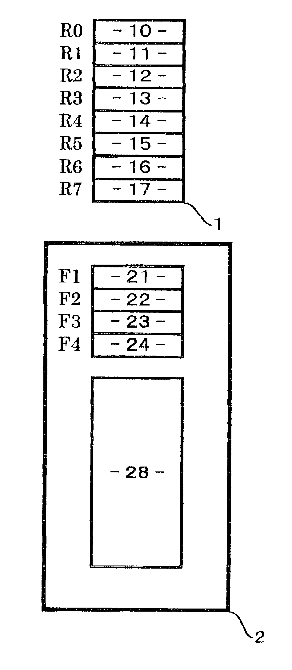
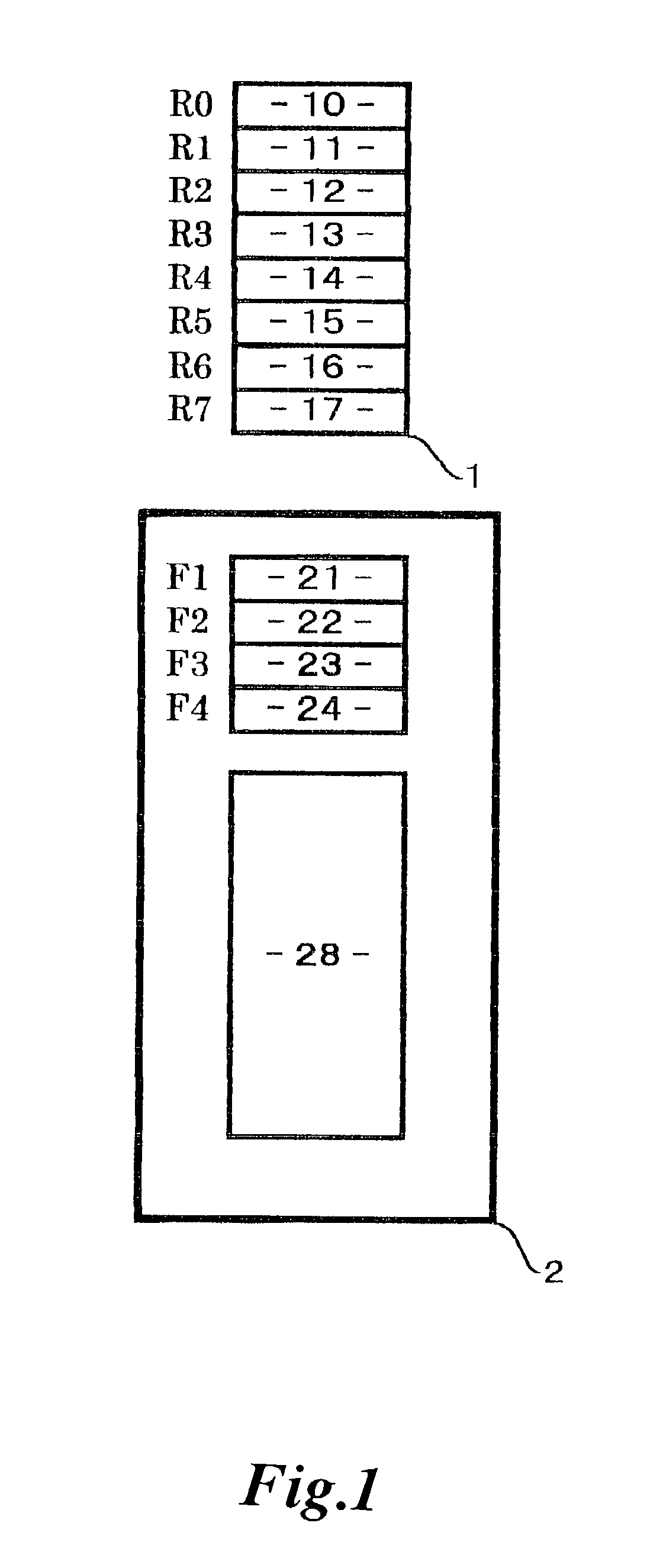
[0019]In the following, a preferred embodiment that materializes the register renaming system according to the present invention will be described referring to the figures. Now, the later-described processor in which the register renaming system according to the present invention is incorporated is a RISC machine that is assumed to have 8 logical registers R0, R1, . . . R7 on the architecture, furnished with 32 physical registers P00, P01, . . . P31 in hardware, and so structured as to be able to have up to four instructions go through the process of register renaming per cycle.

[0020]FIG. 1 is a block diagram of a piece of hardware that is needed for incarnation of the register renaming system according to the present invention. Shown in FIG. 1 are a mapping table 1 and a free list 2.

[0021]Described below is the detailed structure of each of the above-mentioned components.

(A) Mapping Table (MT)

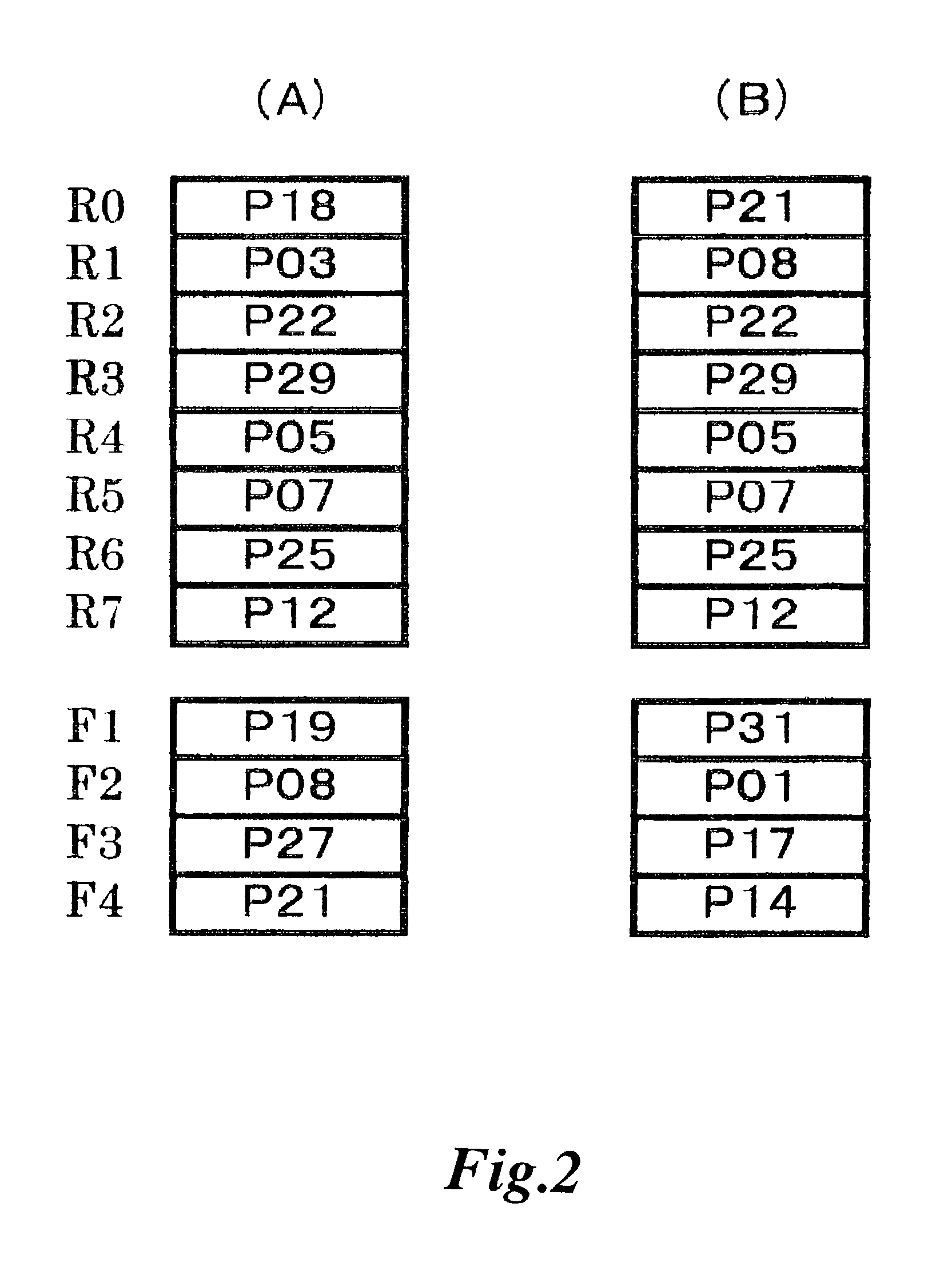
[0022]As shown in FIG. 1, in this embodiment, the mapping table (hereafter, it will be ref...


PUM


Abstract

A register renaming system for a processor based on superscalar architecture that can process a larger number of instructions per cycle by providing a free list to hold unallocated physical-register numbers and a mapping table whose entries are provided in respective correspondence with the logical registers and each designed to hold a physical-register number, and by pipelining where dependency checks among instructions are to be done as a pre-process.

Description

FIELD OF THE INVENTION[0001]The present invention relates to a register renaming system that can process a large number of instructions per clock cycle in a processor based on superscalar architecture capable of out-of-order execution.DESCRIPTION OF THE PRIOR ART[0002]A processor based on superscalar architecture capable of out-of-order execution is equipped with physical registers, the number of which is greater than that of the logical registers prescribed by the architecture. And the technique of dynamic register renaming is applied.[0003]Namely, in each cycle, dependency checks are made by comparing the logical-register numbers shown as operands in the instructions, and the logical-register numbers are respectively renamed to appropriate physical-register numbers so that the dependencies would be dissolved.[0004]For incarnation of register renaming, a technique utilizing a reorder buffer and a technique utilizing a mapping table are known. The technique utilizing a reorder buffe...

Claims


Application Information

Patent Timeline
IPC IPC(8): G06F12/02G06F9/38
CPCG06F9/3836G06F9/3838G06F9/3855G06F9/3867G06F9/384G06F9/3856
Inventor SEKI
Owner SEKI HAJIME
Why Eureka
Try Eureka