Transfer unit and automatic analyzing apparatus having such transfer unit

a transfer unit and automatic analysis technology, applied in the field of transfer units, can solve the problems of affecting the efficiency of analyzing equipment, etc., and achieves the effects of low cost, compact apparatus, and simple construction

Inactive Publication Date: 2007-02-06
BECKMAN COULTER INC
View PDF8 Cites 48 Cited by
  • Summary
  • Abstract
  • Description
  • Claims
  • Application Information

AI Technical Summary

Benefits of technology

[0008]It is an object of the invention to provide an improved transfer unit which overcomes all the disadvantages of the prior art

Problems solved by technology

However, the miniaturization and low cost manufacture of the apparatuses have not been realized to a satisfactory extent because the transfer portion for tips and reaction vessels are imperative.
However, this apparatus suffers several disadvantages from the taking-off members required at all the mounting and dismounting locations, from complicated driving system due to three dimensional movements in longitudinal, transverse and vertical directions required in dismounting operations, and from spaces required to prevent the interference of the taking-off members with other mechanisms of the apparatus.
With this apparatus, however, the complexity in construction of piping, rods, stoppers of rods, control mechanism for the stoppers and transfer mechanism has not been reduce

Method used


Image

  • Transfer unit and automatic analyzing apparatus having such transfer unit
  • Transfer unit and automatic analyzing apparatus having such transfer unit
  • Transfer unit and automatic analyzing apparatus having such transfer unit

Examples


Embodiment Construction

[0045]The present invention will be concretely explained in more detail with reference to the drawings hereinafter.

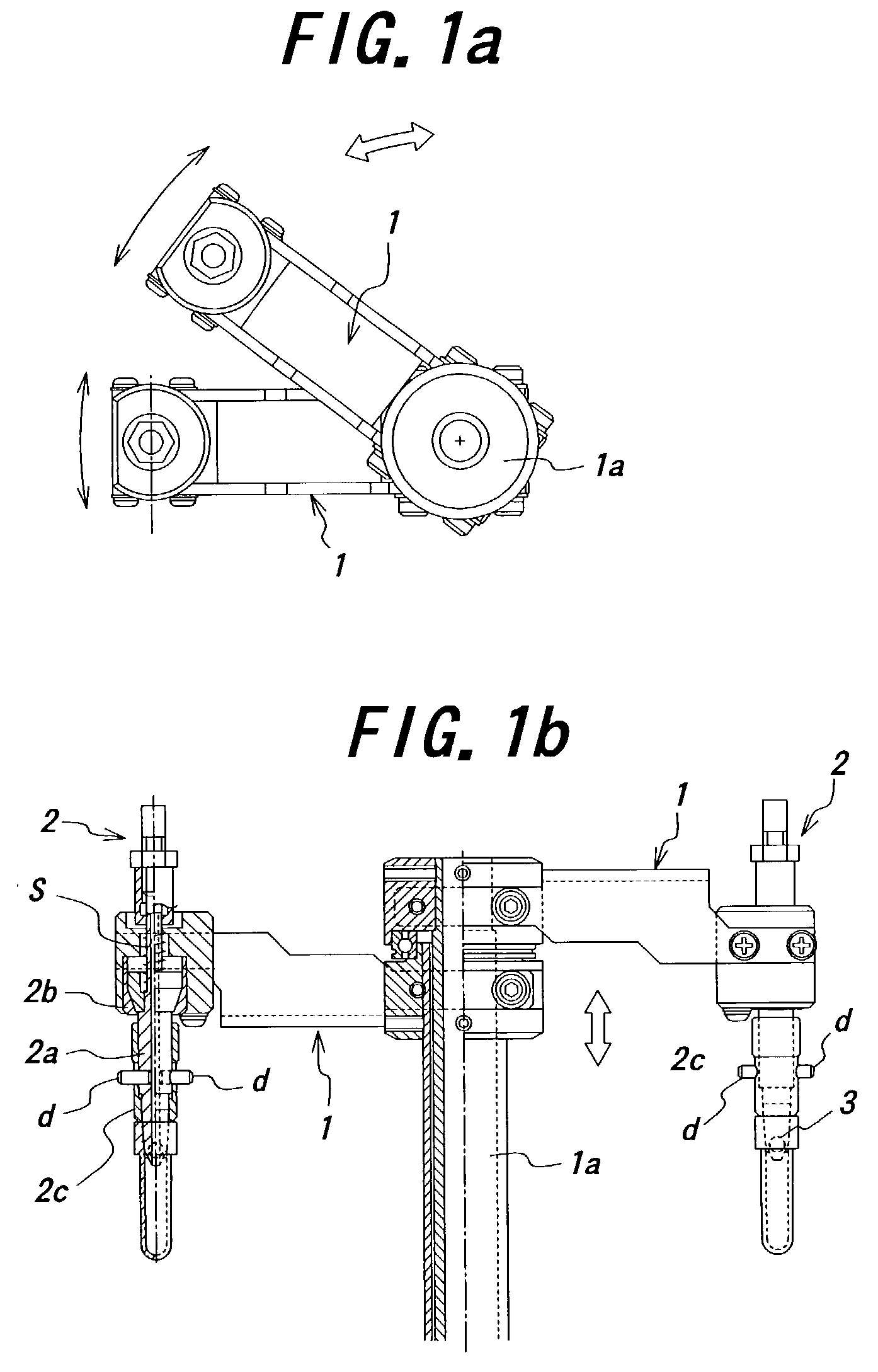
[0046]FIGS. 1a and 1b exemplarily illustrate a transfer unit which comprises arms 1 (two arms in the illustrated embodiment) and holders 2 mounted on the arms 1, respectively. The arms 1 themselves are pivotally supported by a shaft 1a so as to be pivotally moved around the shaft 1a.

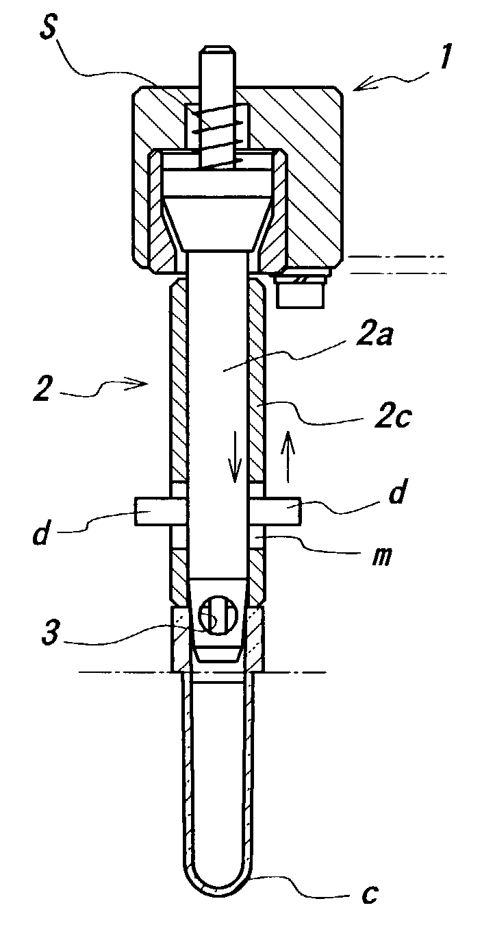
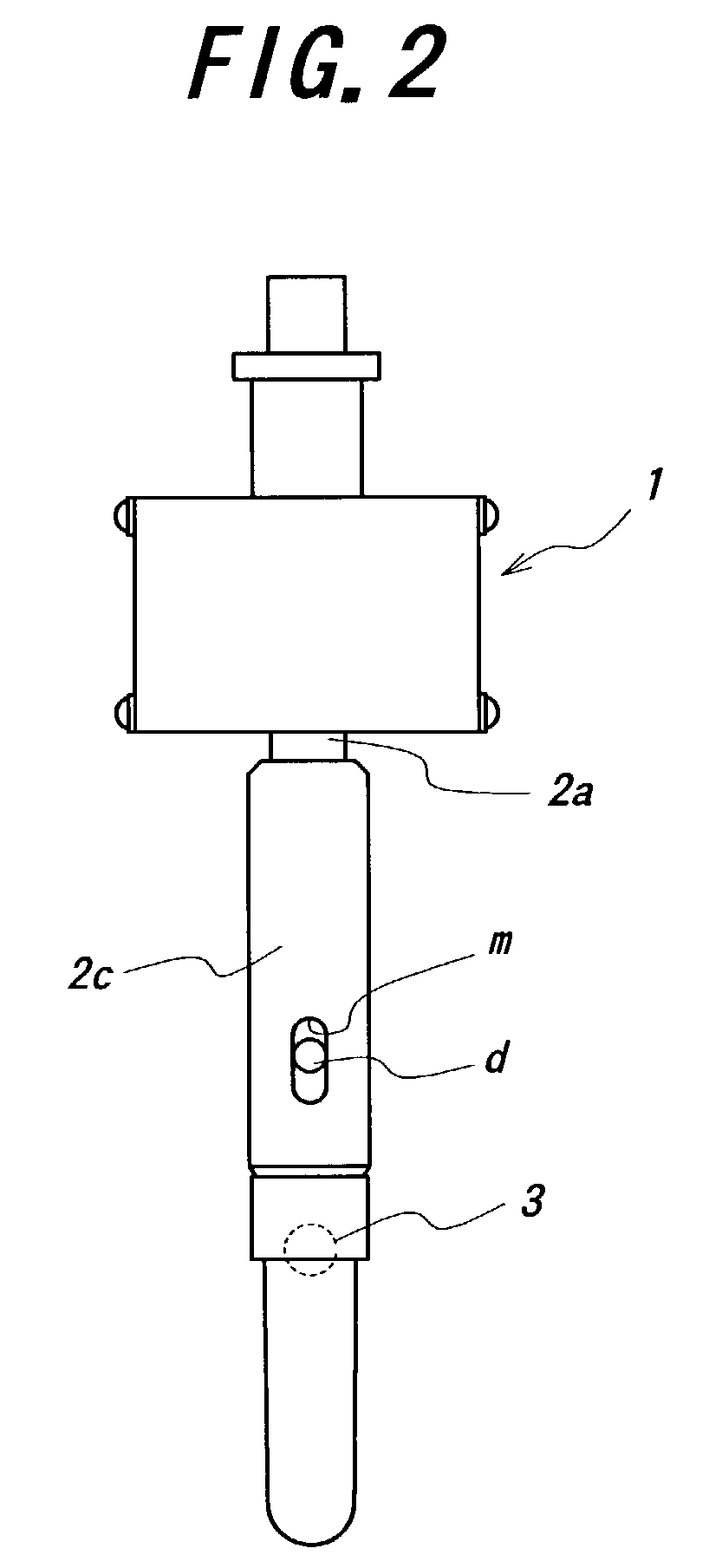
[0047]Each of the holders 2 comprises a rod portion 2a, a rod holding portion 2b for holding the rod portion 2a in a slidably hung state, and a guide portion 2c surrounding and slidable along the rod portion 2a. The guide portion 2c is formed with at least two elongated apertures m extending in the axial direction of the rod portion 2a. On the other hand, the rod portion 2a is provided with protrusions d fixed thereto extending through the elongated apertures m for limiting the movement of the guide portion 2c.

[0048]Moreover, the rod portion 2a is provided at forward or distal end with win...


PUM


Abstract

A transfer unit for transferring members such as reaction vessels having an upper end opening or dispensing tips or the like includes at least one arm pivotally movable about a shaft and a holder mounted on the arm for detachably supporting the member to be transferred. The holder is provided with a rod portion having a distal end adapted to be fitted in the upper end opening of the member to be transferred, a rod holding portion slidably and elastically supporting the rod portion and a guide portion surrounding the rod portion thereabout and sliding along the axis of the rod portion to release the fitting of the member from the distal end of the rod portion. The guide portion is formed with at least two elongated apertures extending in parallel with the axis of the rod portion, and the rod portion is provided with protrusions fixed thereto and extending through the elongated apertures to regulate the movement of the guide portion. By applying such a transfer unit to a chemicobiological or immunity analyzing apparatus, the analyzing operation can be performed at a higher speed with a higher efficiency and a particularly compact analyzing apparatus is possible.

Description

BACKGROUND OF THE INVENTION[0001]This invention relates to a transfer unit capable of transferring reaction vessels, dispensing tips and the like with a simple construction and more particularly to an automatic analyzing apparatus including such a transfer unit.[0002]In the fields of the immunity analysis, chemicobiological analysis and the like, in recent years disposable dispensing tips and reaction vessels have been used in order to avoid errors in data due to carry-over and defective or failed washing. Such dispensing tips and reaction vessels are stored at particular locations and, as required, they are transferred by a transfer mechanism to predetermined positions (for example, dispensing tips after dispensation to discarding positions and reaction vessels to reaction tables or discarding positions) where the dispensing tips and reaction vessels are removed from the transfer mechanism.[0003]On the other hand, recently there has been a strong need for the apparatuses of this ki...

Claims


Application Information

Patent Timeline
IPC IPC(8): B01L3/02G01N35/00G01N35/02G01N35/04G01N35/10
CPCB01L3/0275G01N35/0099G01N35/0098G01N35/025Y10T436/2575G01N2035/103G01N2035/1086Y10T436/11G01N2035/0465
Inventor TAMURA, TOMOAKIMIZUTANI, TAKAYUKI
Owner BECKMAN COULTER INC
Why Eureka
Try Eureka