Solution casting process for producing polymer film

a technology of polymer film and casting process, which is applied in the direction of manufacturing tools, other domestic articles, coatings, etc., can solve the problems of low solubility of cellulose acylate to solvent, low solid content density of dope, and low strength of gel film, etc., to achieve the effect of suppressing wrinkles

Inactive Publication Date: 2007-02-06
FUJIFILM HLDG CORP +1
View PDF3 Cites 72 Cited by
  • Summary
  • Abstract
  • Description
  • Claims
  • Application Information

AI Technical Summary

Benefits of technology

[0006]In view of the foregoing problems, an object of the present invention is to provide a solution casting process for producing polymer film, capable of suppressing wrinkles on the self-supporting cast film, curls on the self-supporting cast film, or residual adhesion of the self-supporting cast film to any of rollers.
[0007]Another object of the present invention is to provide a solution casting process for producing polymer film, capable of efficiently producing the polymer film having high quality in its surfaces and optical characteristics even with a small thickness.
[0012]Furthermore, while the self-supporting cast film is fed, a first surface of the self-supporting cast film is pressed by use of a rotatable decurling roller, to prevent occurrence of a curl on the self-supporting cast film, the first surface having been separated from the support.

Problems solved by technology

However, the solubility of the cellulose acylate to solvent is very low.
Considerable difficulty lies in raising density of solid content in the dope being prepared.
However, shortcomings arise in low strength of the gel film, occurrence of curls in the self-supporting cast film before feeding to the tenter drier machine after stripping from the supporting surface, and occurrence of wrinkles on surfaces of the self-supporting cast film.
If curls occur on the lateral edge portions in the polymer film, a problem is likely to arise in an unstable state of the supporting operation of the lateral edge portions.
If considerably large curls occur, there will be a failure in entry in the tenter drier machine.
Continuous actuation of a system for producing the polymer film may be stopped accidentally.
If wrinkles are created on the surfaces of the self-supporting cast film before being dried, residue of wrinkles will be present on the surfaces of the polymer film as a product, to lower the quality.
This will cause a serious problem in that yield in the production will be too low due to temporarily low quality.

Method used


Image

  • Solution casting process for producing polymer film
  • Solution casting process for producing polymer film
  • Solution casting process for producing polymer film

Examples


examples

[0105]Preferred examples of the invention are hereinafter described. At first, preparation of the dope for use in the experiments is described. Experiment 1 was conducted for observing wrinkles of the self-supporting film and residual adhesion to the self-supporting rollers. For Experiment 1, details of the condition are described with Example 1 and Comparable examples 1–6. Portions of the condition in Comparable examples 1–6 the same as those of Example 1 are not further described. Results in relation to the condition are indicated in Table 1. Then Experiment 2 was conducted for observing occurrence of curls. Specifically, portions of the condition in Experiment 2 the same as those of Experiment 1 are not further described. For Experiment 2, details of the condition are described with Examples 2–4 and Comparable examples 7 and 8. Portions of the condition in Examples 3 and 4 and Comparable examples 7 and 8 the same as those of Example 2 are not further described. Results in relatio...

experiment 1

Example 1

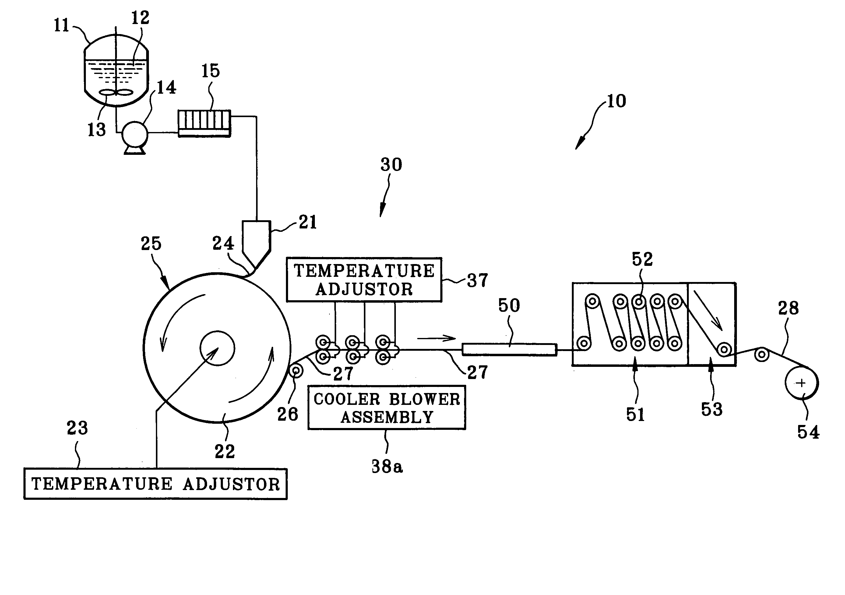
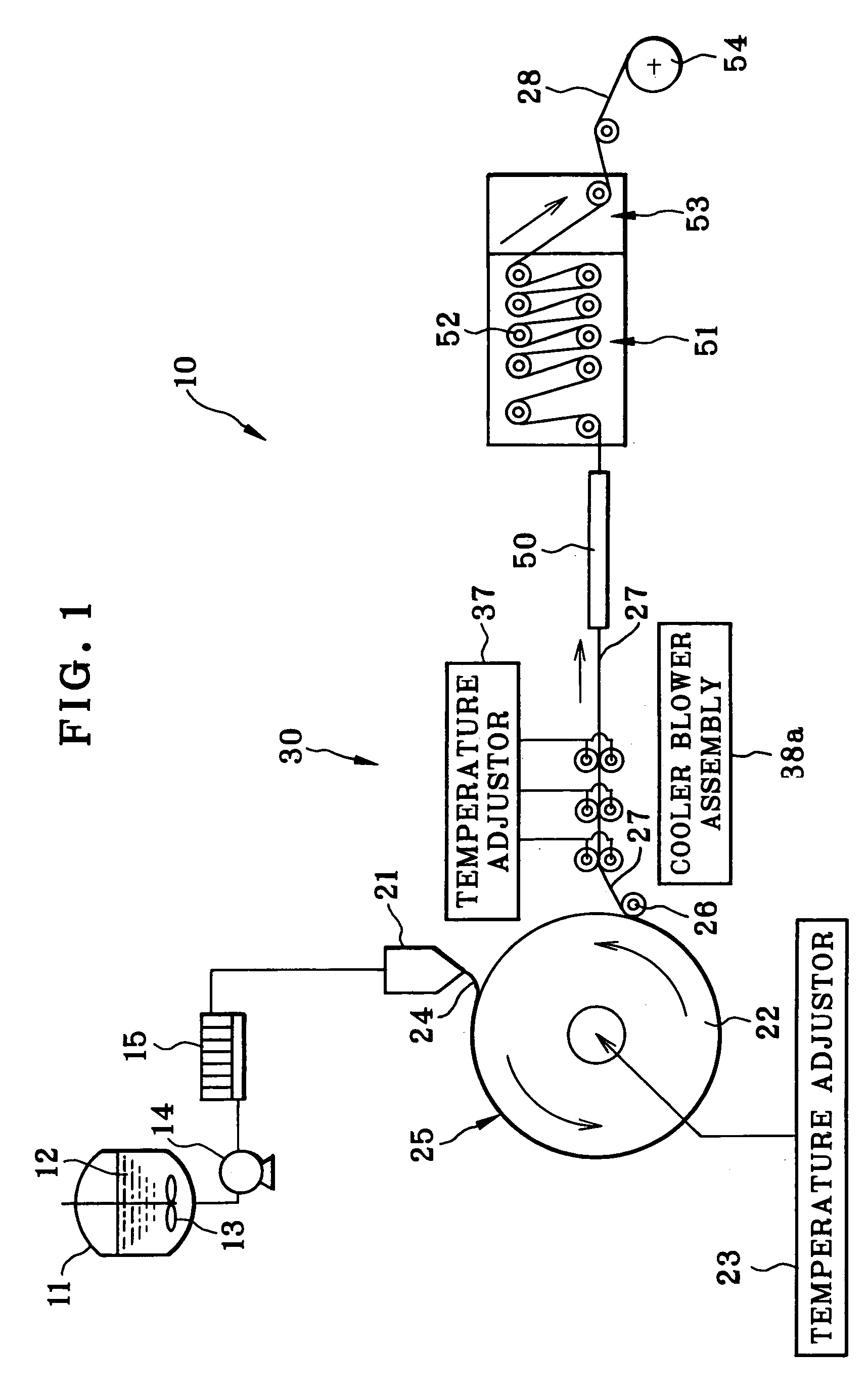
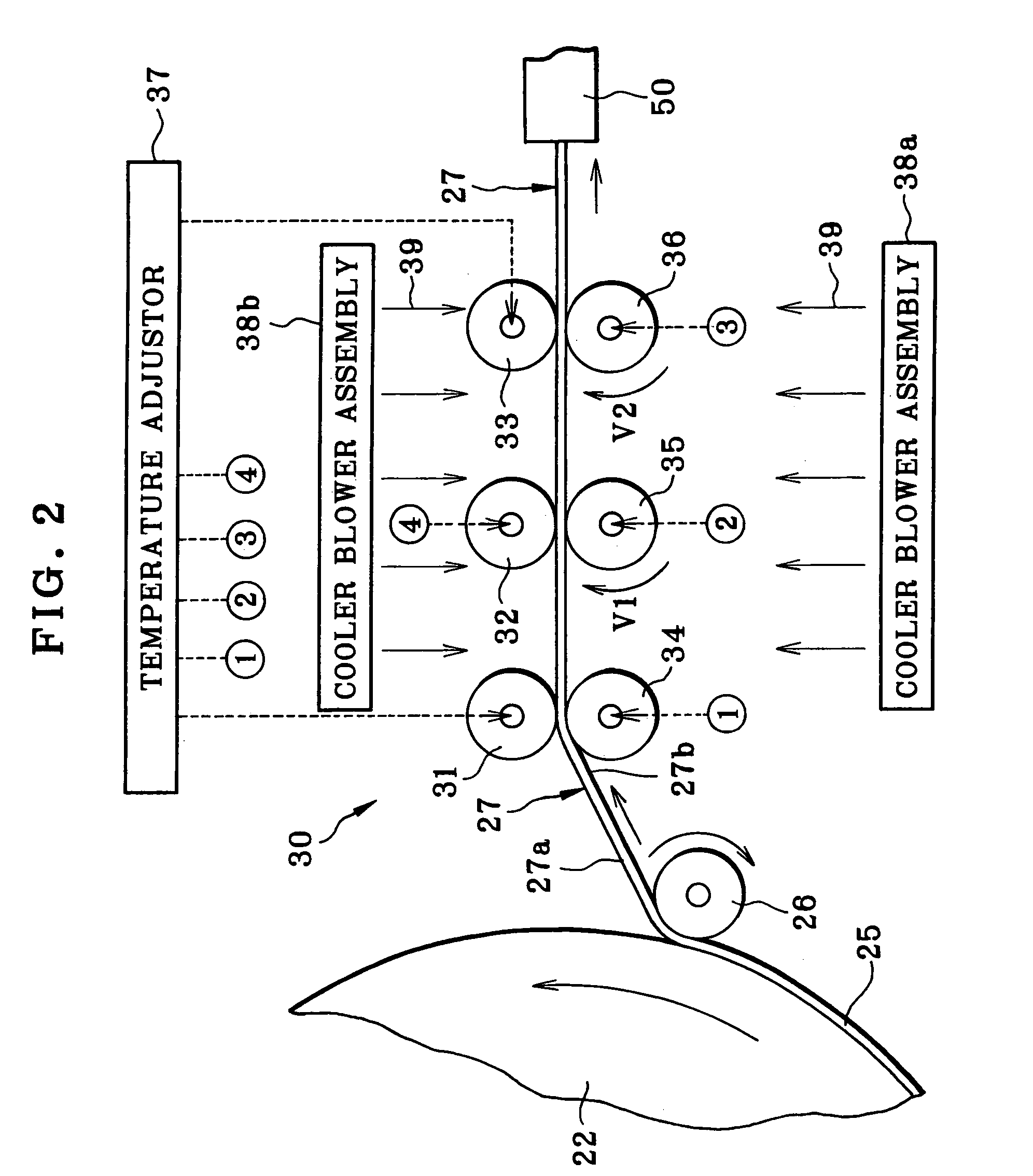
[0110]The polymer film producing system 10 in FIG. 1 was used for the polymer film production. The solution casting die 21 was a coat hanger type of die. A surface of the supporting drum 22 was subjected to plating of hard chromium, and finished according to the mirror surface finish in order to impart a surface roughness of 0.04 S to the supporting drum 22. The feed rollers 31–36 in the transition unit 30 had surface roughness Ra of 0.2 micron, static friction coefficient μ0 of 0.04, and dynamic friction coefficient μ of 0.02. The ratio V2 / V1 of the peripheral speed V2 of the lower feed roller 36 to the peripheral speed V1 of the lower feed roller 35 was determined 1.05. The ratio V1 / V0 of the peripheral speed V1 of the lower feed roller 35 to the peripheral speed V0 of the lower feed roller 34 was also determined 1.05.

[0111]After the above conditions are determined, the dope A at 30° C. was cast on to the supporting drum 22 at the casting speed of 50 meters per minute in ...

comparable examples 1 – 6

Comparable Examples 1–6

[0112]The solution casting of the condition was the same as Example 1 but with differences specifically indicated in Table 1. In Comparable example 2, the self-supporting film was cast with a thickness of 25 microns for the purpose of finely forming the polymer film with a thickness of 17 microns. The condition and results of the experiment are indicated in Table 1.

[0113]

TABLE 1Comp.Comp.Comp.Example 1Example 1Example 2Example 3Modulus (Pa)500,000400,000500,000500,000of longitudinalelasticityThickness60252560(microns) ofthe cast film 27upon beingstrippedTemperature−53−5−5(° C.) of thecast film 27Surface rough-0.20.040.20.04ness Ra(microns) ofthe feed rollersStatic friction0.040.0340.040.04coefficient μ0Dynamic0.020.0170.020.02frictioncoefficient μRatio V2 / V11.051.0021.051.05between theperipheralspeedsStraining rate1.4 × 10−31.3 × 10−31.4 × 10−31.4 × 10⁻³(1 / s) in theextension ofthe cast film 27Occurrence ofACBAwrinklesOccurrence ofACABresidualadhesionComp.Comp....


PUM

PropertyMeasurementUnit
surface temperatureaaaaaaaaaa
temperatureaaaaaaaaaa
thicknessaaaaaaaaaa

Abstract

A solution casting process for producing cellulose triacetate (TAC) film is provided. Bead of dope, which includes cellulose triacetate and solvent, is cast on to a rotating supporting drum, to form self-supporting cast film. The self-supporting cast film is stripped from the supporting drum. The self-supporting cast film is dried while the self-supporting cast film being stripped is fed by feed rollers, to form the cellulose triacetate film. A surface temperature of the feed rollers is set equal to or lower than 0° C. The self-supporting cast film upon being stripped has modulus of longitudinal elasticity equal to or more than 450,000 Pa.

Description

BACKGROUND OF THE INVENTION[0001]1. Field of the Invention[0002]The present invention relates to a solution casting process for producing polymer film. More particularly, the present invention relates to a solution casting process for producing polymer film of which quality of surfaces can be high.[0003]2. Description Related to the Prior Art[0004]JP-A 2001-315147 discloses a solution casting process for producing polymer film. Examples of polymer films include cellulose triacetate (TAC) film, and other cellulose acylate films. The solution casting process is widely used to manufacture a liquid crystal display panel, photosensitive material, and the like. Today, the liquid crystal display panel has been marketed more and more widely. So the production of the polymer film is required to have higher efficiency. For example, a casting speed of the solution casting process is desired to be higher. A thickness of the polymer film is desired to be smaller. To obtain the TAC film as the po...

Claims


Application Information

Patent Timeline
Patent Type & Authority Patents(United States)
IPC IPC(8): B29C35/02B27N3/08B29C41/00C04B40/00B29C41/24B29C35/16B29C41/26B29C41/32B29C41/46B29C41/52B29D7/01B29K1/00B29L7/00
CPCB29C35/16B29C41/26B29D7/01B29C41/32B29K2001/00B29C2035/1658
Inventor ARAI, TOSHINAOYAMAZAKI, HIDEKAZUIKEDA, HITOSHI
Owner FUJIFILM HLDG CORP
Why Eureka
Try Eureka