Method of operating fuel cell and power supply system

Inactive Publication Date: 2007-02-06
MURATA MFG CO LTD
View PDF8 Cites 16 Cited by
  • Summary
  • Abstract
  • Description
  • Claims
  • Application Information

AI Technical Summary

Benefits of technology

[0010]In an embodiment, the step of controlling the supply of air is performed such that the relative humidity of exhausted air is maintained at a humidity level effective for operation of the fuel cell.
[0011]In an embodimen

Problems solved by technology

The moisture thus produced may be condensed into a liquid, and the liquid tends to overflow in an oxygen gas passage, to obstruct

Method used


Image

  • Method of operating fuel cell and power supply system
  • Method of operating fuel cell and power supply system
  • Method of operating fuel cell and power supply system

Examples


Embodiment Construction

[0023]The present invention generally relates to fuel cells. More particularly, the present invention relates to methods of operating fuel cells and power supply systems that include fuel cells to supply power.

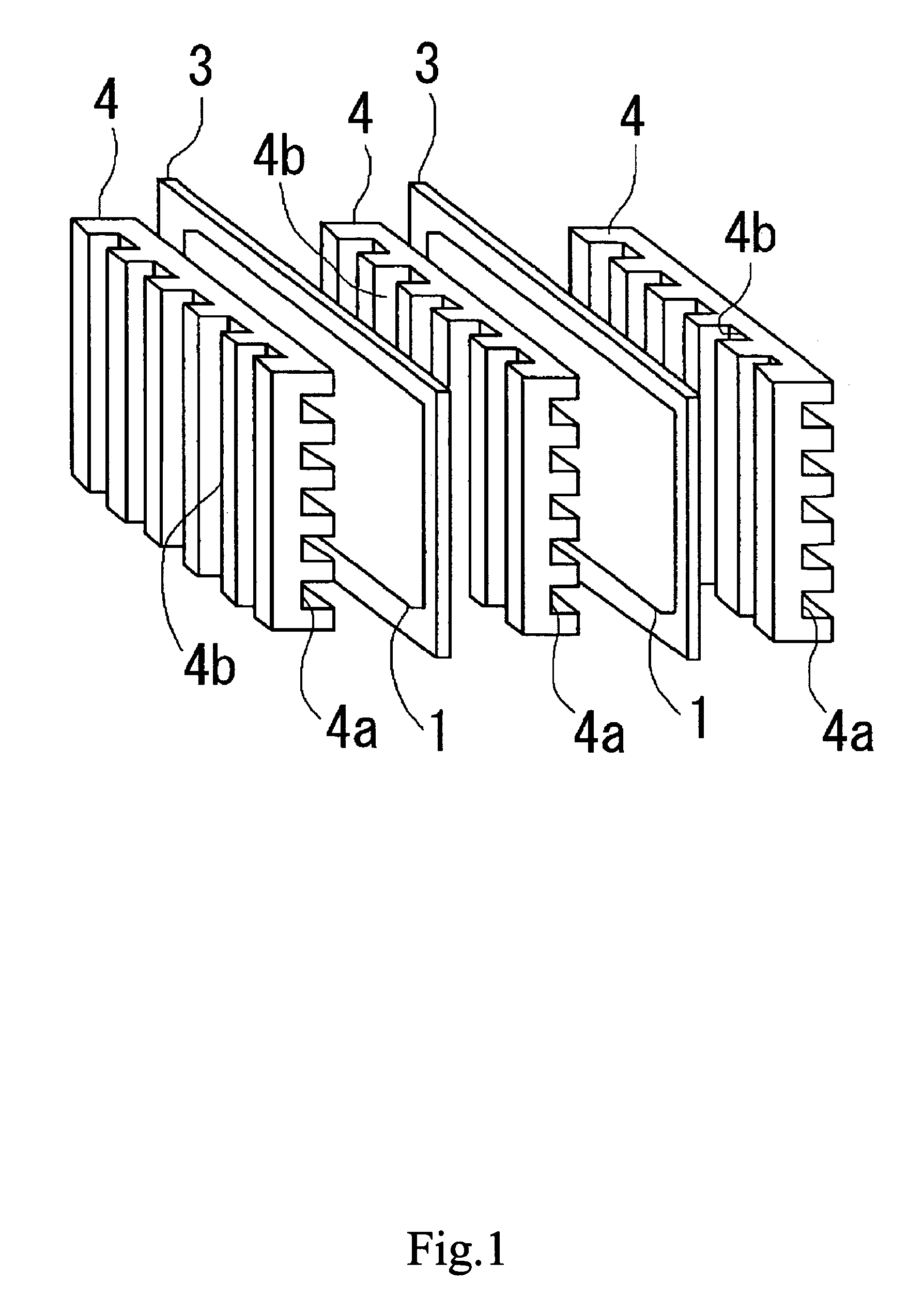
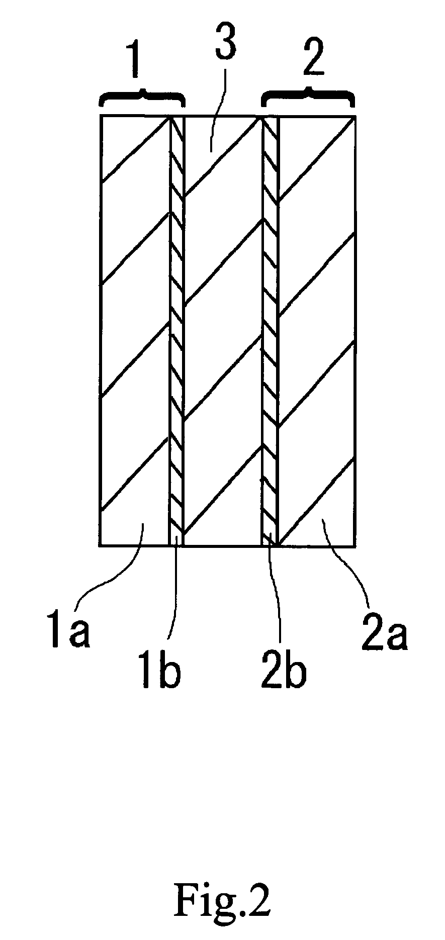
[0024]A basic configuration of a fuel cell as a basic unit of a fuel cell and an electromotive force generating mechanism will be first described. FIG. 1 shows one configuration example of a fuel cell. As shown in FIG. 1, the fuel cell, in an embodiment, is configured by superimposing a fuel electrode 1 to an air electrode 2 via an electrolyte 3, to form a sub-assembly, and sandwiching the sub-assembly between two current collectors 4. It is to be noted that hydrogen representative of a fuel gas is in contact with the fuel electrode 1, and air (oxygen) is in contact with the air electrode2. The current collector 4 is made from a material having a high current collecting performance and a high stability even in an oxidizing water vapor atmosphere. A preferred material of the cu...


PUM


Abstract

Methods of operating a fuel cell and a power supply systems are provided. The methods and systems of the present invention are capable of suppressing condensation of moisture obstructing an air passage without the need of any complicated system configuration. The method of operating a fuel cell includes controlling a supply of air while monitoring a relative humidity of exhausted air. The step of controlling the supply of air can be performed such that the relative humidity of exhausted air becomes equal to or less than a specific humidity. The power supply system including, as a power supply, a fuel cell having an air supply unit, an air exhaust unit, and a fuel gas supply unit includes a humidity sensor provided on the air exhaust unit, and a control mechanism for controlling a supplied amount of air in the air supply unit based on the information provided from the humidity sensor.

Description

CROSS REFERENCE TO RELATED APPLICATIONS[0001]This patent application claims priority to Japanese Patent Document No. P2001-239976 filed on Aug. 7, 2001, the disclosure of which is herein incorporated by reference.BACKGROUND OF THE INVENTION[0002]The present invention relates to a method of operating a fuel cell so as to generate an electromotive force by chemical reaction between oxygen and a fuel gas (for example, hydrogen), and to a power supply system including the fuel cell as a power supply.[0003]Fuel cells are adapted to generate an electromotive force from generators by chemical reaction between hydrogen representative of a fuel gas and oxygen (air) supplied thereto. In general, each fuel cell has a structure that an electrolyte film (proton conductive film) is sandwiched between gas electrodes, to generate a desired electromotive force by chemical reaction generated therein. Such fuel cells are greatly expected to be applied to electric cars or hybrid vehicles, and further, ...

Claims


Application Information

Patent Timeline
IPC IPC(8): H01M8/04H01M8/10
CPCH01M8/04089H01M8/04119H01M8/04522H01M8/04753Y02E60/50H01M8/04156H01M8/04
Inventor NOMOTO, KAZUTOSHI
Owner MURATA MFG CO LTD
Why Eureka
Try Eureka