Dielectric ceramic capacitor comprising non-reducible dielectric

a dielectric capacitor and ceramic technology, applied in the direction of fixed capacitors, basic electric elements, electrical appliances, etc., can solve the problems of high undesirable effects, low specific resistance of ceramic sintered in the reducing atmosphere, and tendency to oxidize under

Inactive Publication Date: 2007-02-06
KEMET ELECTRONICS CORP
View PDF17 Cites 38 Cited by
  • Summary
  • Abstract
  • Description
  • Claims
  • Application Information

AI Technical Summary

Benefits of technology

[0010]A particular advantage of the present invention is the ability to sinter the ceramic in reducing atmosphere at below 1400° C.
[0011]These and other advantages, as will be realized, are provided in a dielectric ceramic comprising:
[0012]about 94–99.9 wt % of a first component defined by Formula 1;[(Ca1-xSrx)O]m(Zr1-yTiy)O2  Formula 1wherein:
[0015]m is at least about 0.85 to no more than about 1.15; and
[0016]about 0.1–5 wt % of a secondary component defined by Formula 2;aSiO2-b[αB2O3-(1−α)Li2O]-cAO  Formula 2wherein:
[0017]a, b and c are selected to lie within the region defined by points A(a=15, b=0, c=85), B(a=70, b=0, c=30), C(a=0, b=70, c=30) and D(a=0, b=15, c=85) of a ternary diagram wherein a is mole percent SiO2; b is mole percent αB2O3-(1−α)Li2O; and c is mole percent AO and a+b+c=100 including the lines BC, CD and AD but excluding the line AB;

Problems solved by technology

One disadvantage with nickel is the propensity to oxidize under those conditions required to sinter the ceramic dielectric.
Unfortunately, ceramics sintered in reducing atmosphere have a lower specific resistance which is highly undesirable.

Method used


Image

  • Dielectric ceramic capacitor comprising non-reducible dielectric
  • Dielectric ceramic capacitor comprising non-reducible dielectric
  • Dielectric ceramic capacitor comprising non-reducible dielectric

Examples


examples

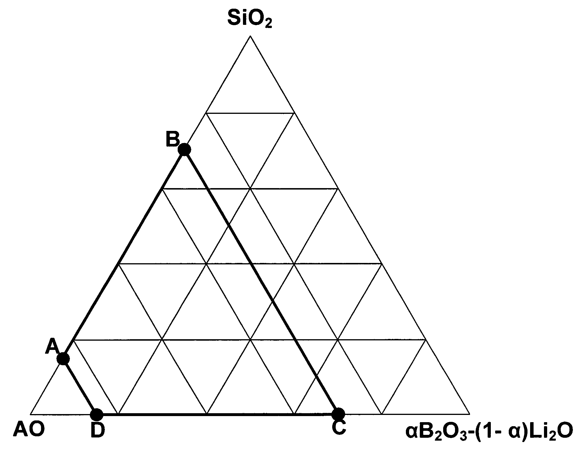
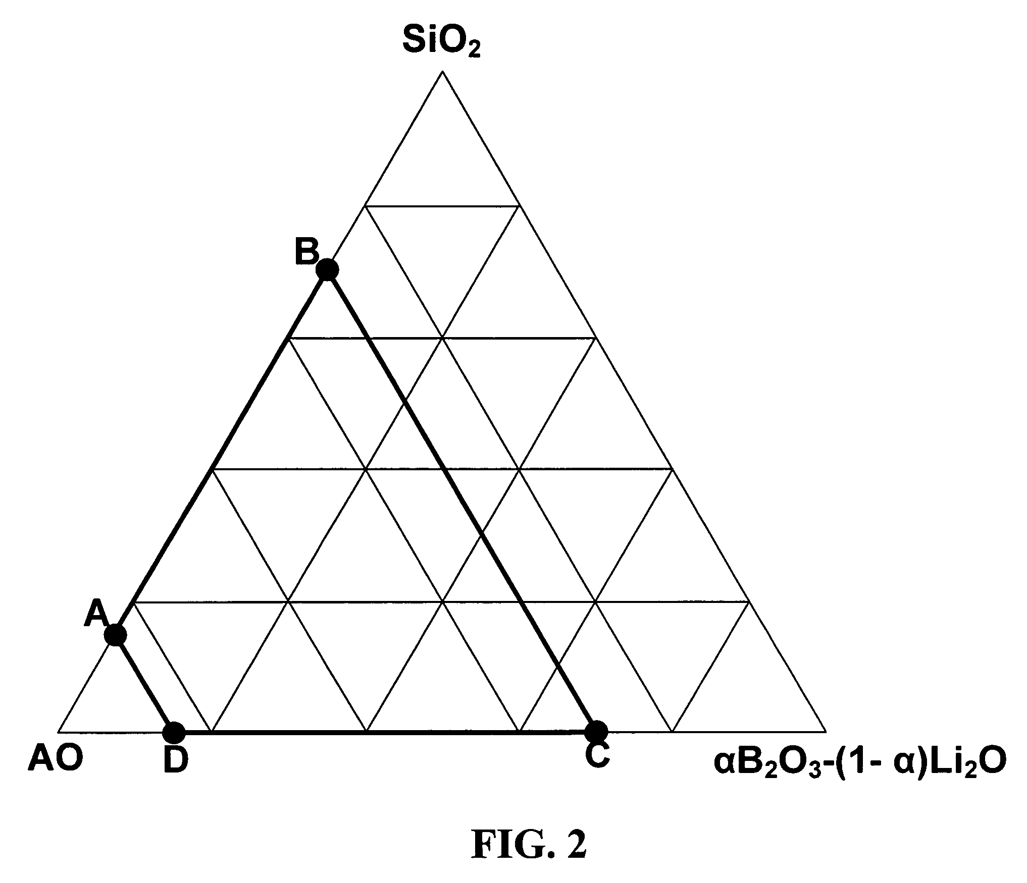
[0066]A powder of [(Ca1-xSrx)O]m(Zr1-yTiy)O2 was used as the primary component in all the following examples. The powder was prepared by calcination from CaCO3, SrCO3, ZrO2 and TiO2 in ratios to achieve a composition with x=0.3, y=0.03 and m=1.000. The typical median particle size of the calcined powder was 0.7 μm and the specific surface area was 4.5 m2 / g. Glass powders for the secondary components were obtained by mixing raw materials of CaCO3, SrCO3, SiO2 and B2O3, melting, quenching and milling. Table 1 gives the formulation of the glass powders used.

[0067]

TABLE 1GlassSiO2B2O3CaOSrOPowder No.(mol %)(mol %)(mol %)(mol %)A3020500B30203515C30202030

[0068]Ceramic formulations were prepared by mixing and milling mixtures of the primary component, a secondary component (glass powder+additive) and manganese dioxide in water with a binder and plasticizer in order to prepare ceramic slurries. Table 2 and 3 give the ceramic formulations prepared with this process. Table 2 gives the actual ...


PUM

PropertyMeasurementUnit
dielectric constantaaaaaaaaaa
temperatureaaaaaaaaaa

Abstract

A dielectric ceramic, and capacitor with the ceramic, wherein the ceramic has: about 94–99.9 wt % a first component defined by Formula 1;[(Ca1-xSrx)O]m(Zr1-yTiy)O2Formula 1wherein:x is no more than about 0.6; andy is no more than about 0.1; andm is at least about 0.85 to no more than about 1.15; andabout 0.1–5 wt % a secondary component defined by Formula 2;aSiO2-b[αB2O3-(1−α)Li2O]-cAOFormula 2wherein:a, b and c are selected to lie within the region defined by points A(a=15, b=0, c=85), B(a=70, b=0, c=30), C(a=0, b=70, c=30) and D(a=0, b=15, c=85) of a ternary diagram wherein a is mole percent SiO2; b is mole percent αB2O3-(1−α)Li2O; and c is mole percent AO and a+b+c=100 including the lines BC, CD and AD but excluding the line AB;α is 0 to 1;A is selected from Mg, Ca, Sr, Ba or a combination thereof; and0–2 wt % MnO2.

Description

BACKGROUND OF THE INVENTION[0001]The present invention relates to a dielectric ceramic capacitor comprising alternating layers of electrodes and ceramic wherein the ceramic comprises calcium zirconium compounds in a main component.[0002]Ceramic capacitors are known to comprise alternating layers of inner electrodes and ceramic dielectric. There has been, and continues to be, a desire to lower the cost of capacitors without sacrificing the quality. There has also been, and continues to be, a desire to lower the size of capacitors without sacrificing either the quality or capacitance. These desires are often at odds leading those of skill in the art towards continual efforts to advance the art of capacitors and the manufacture thereof.[0003]One advance is the use of nickel as the electrode metal. Nickel has advantages in that the cost is low compared to noble metals such as silver and palladium and the resistance properties are suitable for use in a capacitor. One disadvantage with ni...

Claims


Application Information

Patent Timeline
Patent Type & Authority Patents(United States)
IPC IPC(8): C04B35/465C04B35/47
CPCH01G4/30H01G4/1227C04B35/49B32B2311/22C04B2235/3203C04B2235/3206C04B2235/3208C04B2235/3213C04B2235/3215C04B2235/3267C04B2235/3409C04B2235/3418C04B2235/36C04B2235/5409C04B2235/5445C04B2235/656C04B2235/6582C04B2235/6588C04B2235/96C04B2237/346C04B2237/348C04B2237/405C04B35/465C04B35/47
Inventor PINCELOUP, PASCAL G.BEESON, JAMES J.
Owner KEMET ELECTRONICS CORP
Why Eureka
Try Eureka