
Boost DC/DC converter

a dc/dc converter and converter technology, applied in the direction of dc-dc conversion, power conversion systems, instruments, etc., can solve the problems of reducing system efficiency and increasing overall input power loss, and achieve the effect of improving system efficiency and optimizing system efficiency

Active Publication Date: 2007-02-06
CHUNGHWA PICTURE TUBES LTD
View PDF6 Cites 36 Cited by
  • Summary
  • Abstract
  • Description
  • Claims
  • Application Information

AI Technical Summary

Benefits of technology

[0008]Accordingly, the present invention is directed to provide a boost DC / DC converter, which can enable the system to selectively operate in the pulse width modulation mode, the pulse frequency modulation mode or the mixed pulse mask mode respectively through the mask signal corresponding to the load current when the system is in light load, medium load or heavy load. The boost DC / DC converter is able to achieve optimal system efficiency so as to improve the system efficiency of the conventional boost DC / DC converter when the system is in light load.
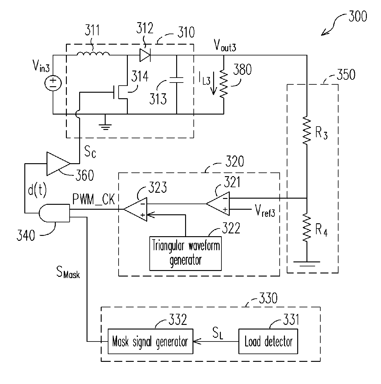
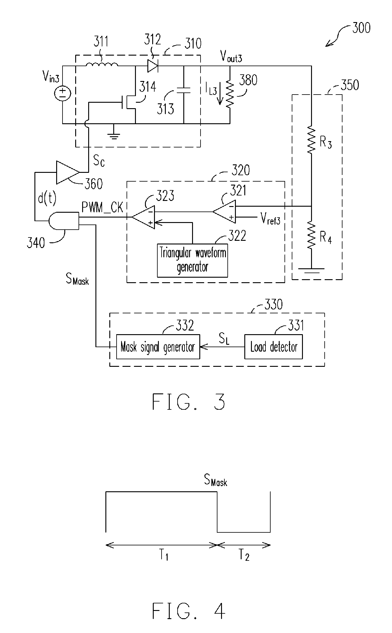
[0017]In the boost DC / DC converter of the present invention, when the system is in heavy load, the pulse width modulation mode is used; when the system is in light load, the pulse frequency modulation mode is used; and when the system is neither in heavy load nor in light load, but in medium load, the mixed pulse mask mode is used by the system. That is, the boost DC / DC converter of the present invention can determine if the mask signal's mode is the pulse width modulation mode or the pulse frequency modulation mode or the mixed pulse mask mode according to the load current. No matter the system is in heavy load or light load, the switching times of the power transistor can be adjusted by the mask signal, so that unnecessary power loss on the power transistor can be reduced and the system converting efficiency can be enhanced.

Problems solved by technology

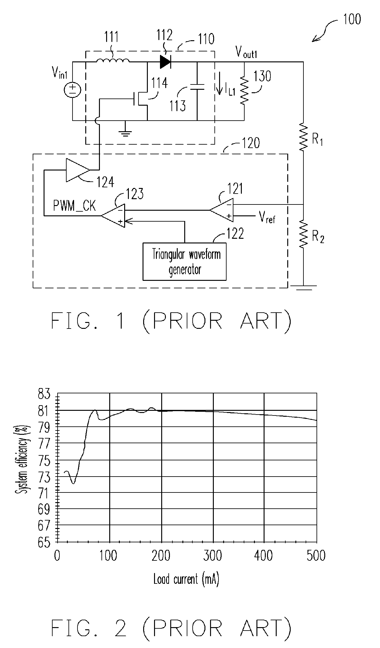
Even in light load, the power transistor 114 performs the switching at same frequency as in heavy load, thus consuming unnecessary switching power on the power transistor 114, increasing overall input power loss and reducing system efficiency.

Method used


Image

  • Boost DC/DC converter
  • Boost DC/DC converter
  • Boost DC/DC converter

Examples


Embodiment Construction

[0030]The description below is an embodiment of the present invention. FIG. 3 is a schematic block diagram of a boost DC / DC converter 300 according to an embodiment of the present invention. The boost DC / DC converter 300 comprises a switched boost circuit 310, a pulse width modulation circuit 320, a mask circuit 330, an AND gate 340, a voltage dividing circuit 350 and a driver 360.

[0031]The switched boost circuit 310 provides an output voltage Vout3 according

[0032]to a control signal Sc and an input voltage Vin3, wherein the output voltage Vout3 is greater than the input voltage Vin3. And the pulse width modulation circuit 320 can output a pulse width modulation signal PWM_CK according to the divided voltage of the output voltage Vout3 (Vout3×R4 / (R3+R4)) and a reference voltage Vref3. The mask circuit 330 outputs a mask signal Smask according to a load current IL3. The AND gate 340 receives the pulse width modulation signal PWM_CK and the mask signal Smask, and then provides a contr...


PUM


Abstract

A boost DC / DC converter, including a mask circuit, a switched boost circuit, a pulse width modulation (PWM) circuit and an AND gate, is provided. The mask circuit is used to output a mask signal according to a load current. In the present invention, the system can selectively operate in the pulse width modulation mode, the pulse frequency modulation (PFM) mode or the mixed pulse mask mode according to the mask signal corresponding to the load current when the system is under light load, medium load or heavy load respectively, so as to achieve optimal system efficiency.

Description

BACKGROUND OF THE INVENTION[0001]1. Field of Invention[0002]The present invention relates to a boost DC / DC converter. More particularly, the present invention relates to a boost DC / DC converter applying the pulse modulation technology.[0003]2. Description of Related Art[0004]In power supply converting system, the load variation would correspondingly affect the power supply converting efficiency, so in case of full load or a big load, it is still preferred that the system maintains high efficiency and stable power conversion. As to application, the processor, the random access memory, the display or the hand phone etc., are certainly not in full load all the time, especially the mobile communication products, such as the hand phone, which is in power saving mode most of the time, therefore a power supply converting system which is able to maintain high efficiency under any load state is very important.[0005]FIG. 1 is a schematic block diagram of a conventional boost DC / DC converter 1...

Claims


Application Information

Patent Timeline
IPC IPC(8): G05F1/40
CPCH02M3/157
Inventor CHEN, KE-HORNGPENG, CHIEN-FANGCHEN, SHIH-MINHSU, MING-TAN
Owner CHUNGHWA PICTURE TUBES LTD
Learn More