
Temperature field controlled scheduling for processing systems

a technology of processing system and temperature field, applied in the direction of multi-programming arrangement, generating/distributing signals, instruments, etc., can solve the problems of system failure or errant behavior, inconvenient recharge of batteries, and serious energy consumption

Inactive Publication Date: 2007-02-06
TEXAS INSTR INC
View PDF24 Cites 104 Cited by
  • Summary
  • Abstract
  • Description
  • Claims
  • Application Information

AI Technical Summary

Benefits of technology

[0011]The present invention provides a method and apparatus for controlling the execution of multiple tasks in a processing circuit including several modules, where temperature-associated information is determined at various areas of the processing circuit. Tasks are executed on the plurality of modules of the processing circuit responsive to the temperature-associated information in order to prevent problems associated with one or more areas exceeding a temperature threshold.
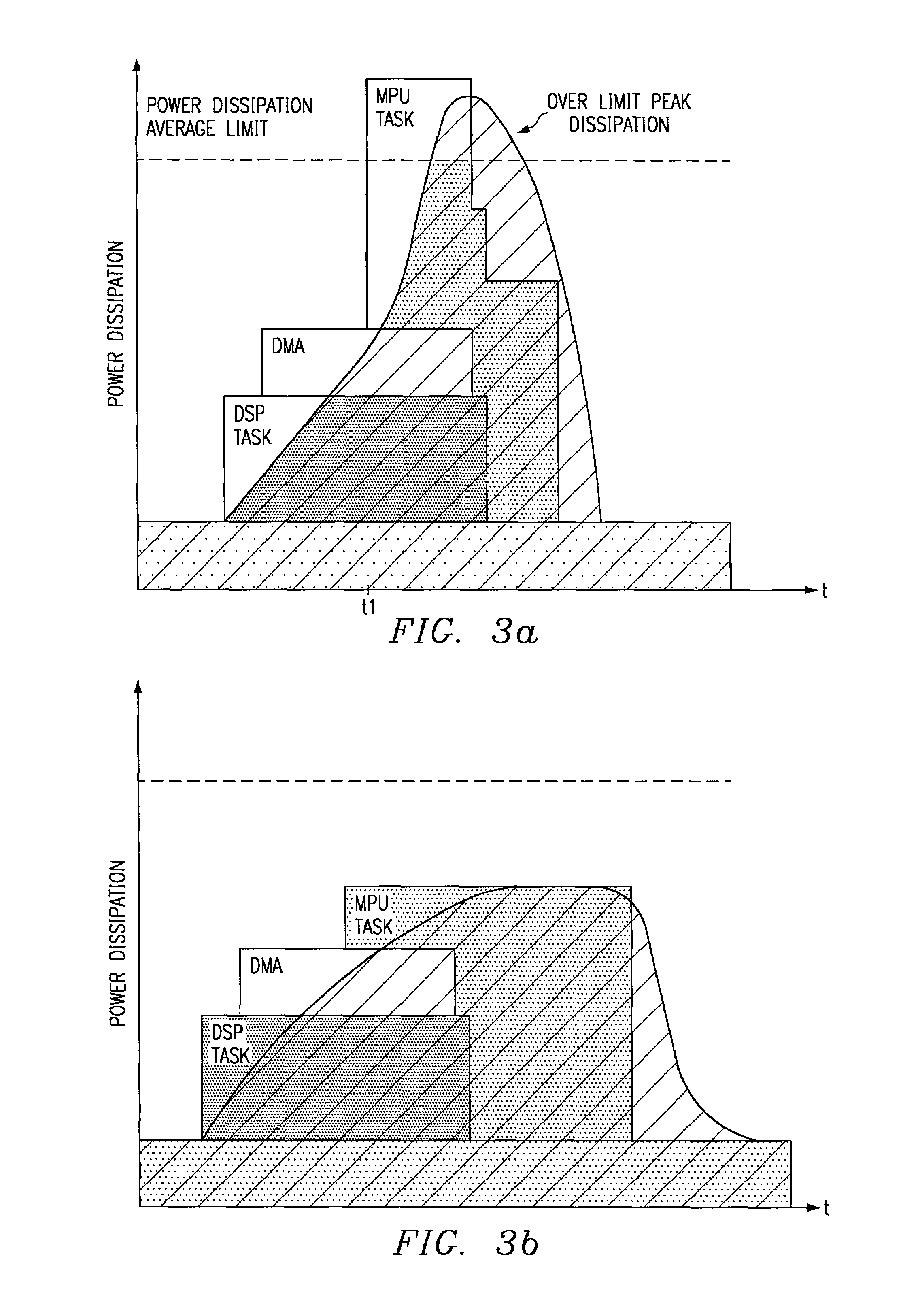
[0012]The present invention provides significant advantages over the prior art by providing a fully dynamic energy management based on the temperature, or estimated temperature, of various areas of a device. As the tasks executed in the device change, the energy management can build new scenarios to ensure that temperature thresholds are not exceeded in any area of the device.

Problems solved by technology

Presently, energy consumption has become a serious issue.
It is desirable to maximize the battery life in these systems, since it is inconvenient to recharge the batteries after short intervals.
If tasks (application processes) require multiple systems on the integrated circuit to draw high levels of current, it is possible that the circuit will overheat, causing system failure or errant behavior.
In the future, applications executed by integrated circuits will be more complex and will likely involve multiprocessing by multiple processors, including MPUs, DSPs, coprocessors and DMA channels in a single integrated circuit (hereinafter, a “multiprocessor system”).
This is especially true in wireless multimedia appliances domain, where severe cost constraints require the use of a small, low pin count, low cost, packaging technology.
Accordingly, the tasks that a multiprocessor system will be able to handle without overheating will become uncertain.

Method used


Image

  • Temperature field controlled scheduling for processing systems
  • Temperature field controlled scheduling for processing systems
  • Temperature field controlled scheduling for processing systems

Examples


first embodiment

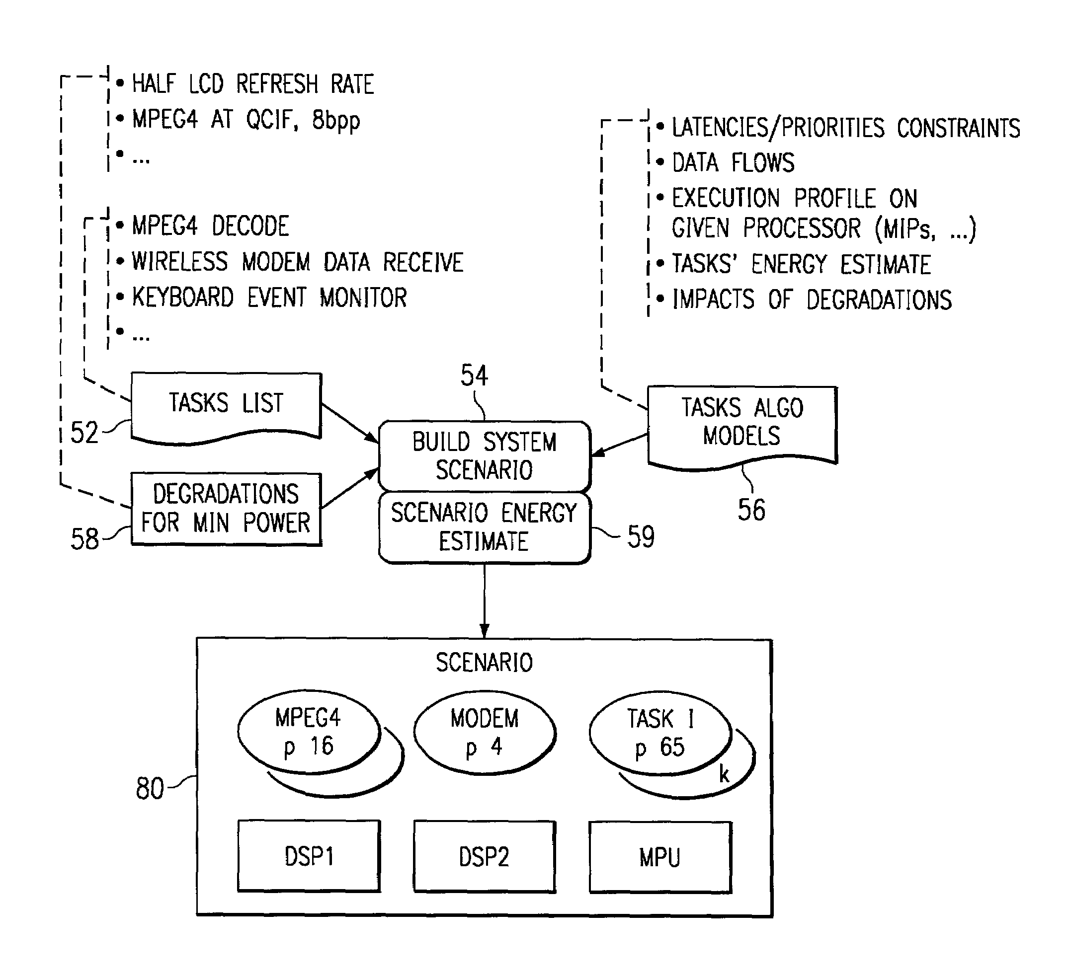
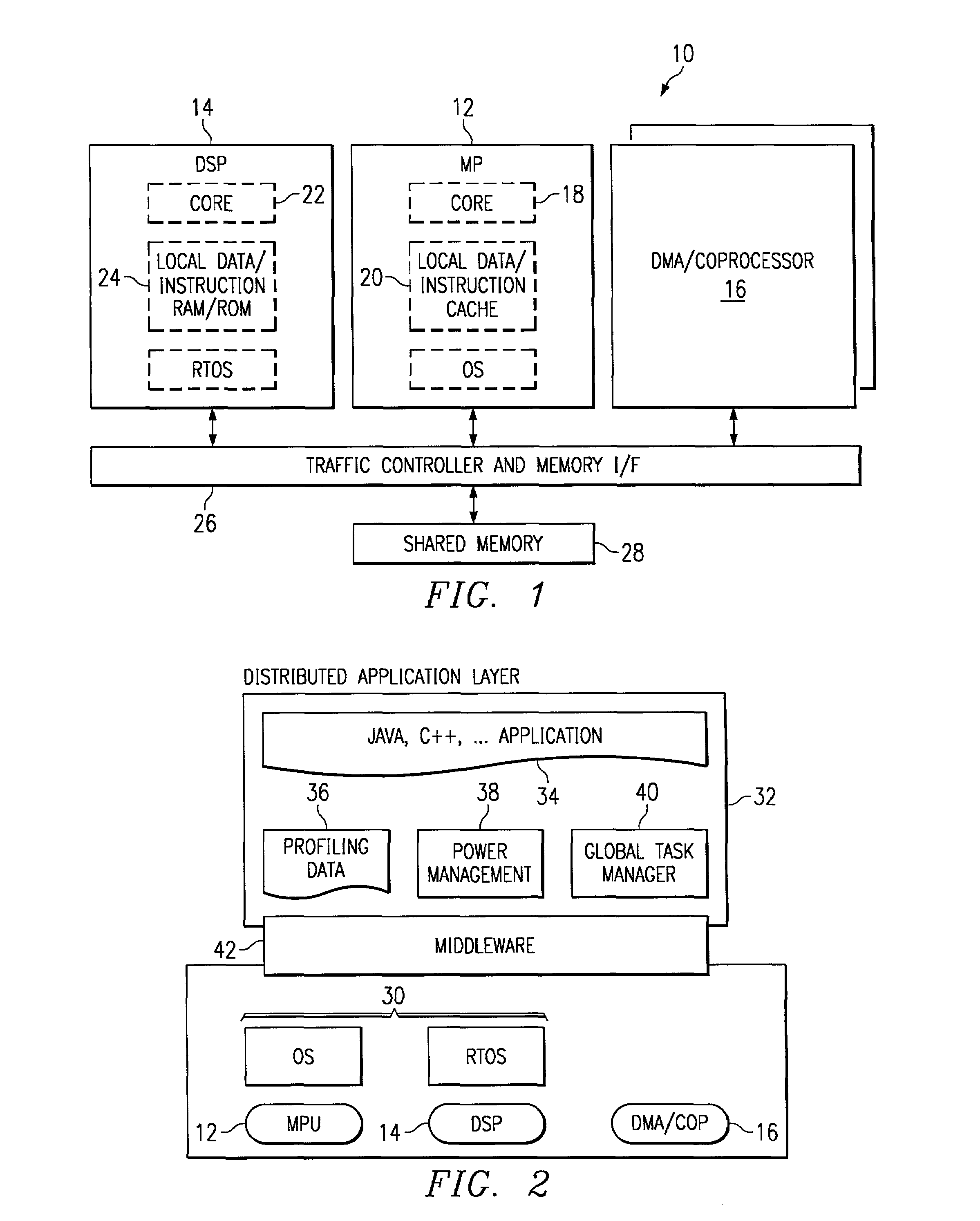
[0035]FIG. 4a illustrates a flow chart describing operation of the power management tasks 38. In block 50, the power management tasks are invoked by the global scheduler 40, which could be executed on the MPU 12 or one of the DSPs 14; the scheduler evaluate the upcoming application and splits it into tasks with associated precedence and exclusion rules. The task list 52 could include, for example, audio / video decoding, display control, keyboard control, character recognition, and so on. In step 54, the task list 52 is evaluated in view of the task model file 56 and the accepted degradations file 58. The task model file 56 is part of the profiles 36 of the distributed applications layer 32. The task model file 56 is a previously generated file that assigns different models to each task in the task list. Each model is a collection of data, which could be derived experimentally or by computer aided software design techniques, which defines characteristics of the associated task, such a...

second embodiment

[0040]FIG. 4b is a flow chart describing operation of the power management tasks 38. The flow of FIG. 4b is the same as that of FIG. 41, except when the scenario construction algorithm is invoked (new task, task delete, real time event) in step 50, instead of choosing one new scenario, n different scenarios that match the performances constraints can be pre-computed in advance and stored in steps 54 and 59, in order to reduce the number of operations within the dynamic loop and provide faster adaptation if the power computed in the tracking loop leads to current scenario rejection in block 74, In FIG. 4b, if the scenario is rejected, another pre-computed scenario is selected in block 65. Otherwise the operation is the same as shown in FIG. 4a.

[0041]FIGS. 5–8 illustrate the operation of various blocks of FIG. 3 in greater detail. The build system block 54 is shown in FIG. 5. In this block, a task list 52, a task model 56, and a list of possible task degradations 58 are used to gener...


PUM


Abstract

A multiprocessor system (10) includes a plurality of processing modules, such as MPUs (12), DSPs (14), and coprocessors / DMA channels (16). Power management software (38) in conjunction with profiles (36) for the various processing modules and the tasks to executed are used to build scenarios which meet predetermined power objectives, such as providing maximum operation within package thermal constraints or using minimum energy. Actual activities associated with the tasks are monitored during operation to ensure compatibility with the objectives. The allocation of tasks may be changed dynamically to accommodate changes in environmental conditions and changes in the task list. Temperatures may be computed at various points in the multiprocessor system by monitoring activity information associated with various subsystems. The activity measurements may be used to compute a current power dissipation distribution over the die. If necessary, the tasks in a scenario may be adjusted to reduce power dissipation. Further, activity counters may be selectively enabled for specific tasks in order to obtain more accurate profile information.

Description

[0001]This application claims priority to European Application Serial No. 00402948.4, filed Oct. 24, 2000 (TI-31362EU). U.S. patent application Ser. No. 6,751,706 (TI-31366US) is incorporated herein by reference.BACKGROUND OF THE INVENTION[0002]1. Technical Field[0003]This invention relates in general to integrated circuits and, more particularly, to managing energy in a processor.[0004]2. Description of the Related Art[0005]For many years, the focus of processor design, including designs for microprocessor units (MPUs), co-processors and digital signal processors (DSPs), has been to increase the speed and functionality of the processor. Presently, energy consumption has become a serious issue. Importantly, maintaining low energy consumption, without seriously impairing speed and functionality, has moved to the forefront in many designs. Energy consumption has become important in many applications because many systems, such as smart phones, cellular phones, PDAs (personal digital as...

Claims


Application Information

Patent Timeline
IPC IPC(8): H04B1/38G06F1/32G06F9/46G06F1/00G06F1/20
CPCG06F1/206G06F1/3203G06F1/329G06F11/0724G06F9/4893Y02B60/1275Y02B60/144Y02D10/00
Inventor CHAUVEL, GERARDD'INVERNO, DOMINIQUEEDWARDS, DARVIN R.
Owner TEXAS INSTR INC
Learn More