Construction of a medical electrical lead

a technology of electrical leads and construction, which is applied in the field of lead assemblies, can solve the problems of adding complexity in the manufacture of pacing and defibrillation, and achieve the effects of reducing the overall size of the lead, reducing the cycle time, and reducing the process steps

Active Publication Date: 2007-02-06
PACESETTER INC
View PDF10 Cites 96 Cited by
  • Summary
  • Abstract
  • Description
  • Claims
  • Application Information

AI Technical Summary

Benefits of technology

[0016]Further advantages will become apparent by comparing the current manner of assembly of a lead with that being proposed. The proposed assembly process employing a lead configuration as taught in this disclosure results in a significant reduction of the process steps.
[0017]This reduction of steps translates to a reduction in cycle time and would thereby result in either allowing operators to work on alternate tasks in the saved time or enabling manufacture of a larger number of units can be produced in the same amount of time.
[0018]In another embodiment, the cables are braided thereby reducing the overall size of the lead.

Problems solved by technology

Advances in technology have given rise to added complexity in the manufacture of pacing and defibrillation leads.
(1) current leads utilize an insulation tubing furbished with lumina. Construction of the lead entails having to string the cables through the lumina along the length of the entire lead. This often poses problems resulting in kinking of the cables. The procedure just described places restrictions on the size of the lumina. To allow ease of stringing of the cable conductors and to account for lot to lot variation, a certain clearance is allowed between the cables and the walls of the lumen. This in turn could allow for the cables to move around within the lumen space, which could result in “internal abrasion” This is especially a concern if the cable conductors are not coated, for example, with a fluoropolymer.

Method used


Image

  • Construction of a medical electrical lead
  • Construction of a medical electrical lead
  • Construction of a medical electrical lead

Examples


Embodiment Construction

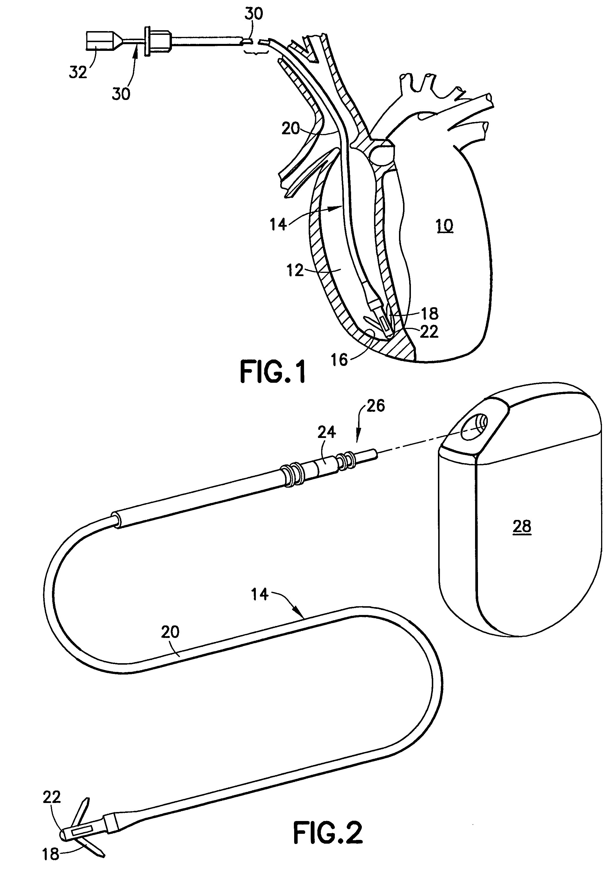
[0037]Refer now to the drawings and, initially, to FIG. 1 which illustrates a diagrammatic perspective view, partially cut away and shown in section, of a heart 10 into the right ventricle 12 of which is inserted a body implantable lead 14 of the endocardial type incorporating features of the present invention. Although the present invention will be described with reference to the embodiments shown in the drawings, it should be understood that the present invention can be embodied in many alternate forms or embodiments. In addition, any suitable size, shape or type of elements or materials could be used. The lead 14 is attached to an interior wall 16 of the heart 10 by means of fixing tines 18, for example, which engage the tissue or trabeculae of the heart.

[0038]As further illustrated, the lead 14 also includes an insulating sheath 20 interconnecting a distal electrode 22 secured adjacent the interior wall 16 and an electrical connector 24 (see FIG. 2) at a proximal end 26 to which...


PUM


Abstract

An implantable cardiac stimulation lead system for use with an implantable stimulation device includes at least a pair of conductors, braided together and extending between proximal and distal ends and co-extruded with flexible resilient insulation material. Each conductor may be a multi-strand cable composed of MP35N or DFT and have its outer peripheral surfaces coated with insulative material. An electrical connector is coupled to the proximal end of the lead system for connection with a stimulation device and includes terminals electrically connected to the conductors. The proximal connector is thereby electrically coupled to a distal tip electrode and to at least one electrode proximally spaced from the distal tip electrode. The lead system may include an elongated tubular lead body of flexible resilient insulative material having a longitudinally extending lumen for receiving a stylet for aid in implanting the lead system. Alternatively, an introducer sheath may be employed for implantation.

Description

FIELD OF THE INVENTION[0001]The present invention relates generally to implantable medical devices for providing stimulating pulses to selected body tissue, for example, the heart, and more particularly, to the lead assemblies connecting such devices with the tissue to be stimulated.BACKGROUND OF THE INVENTION[0002]Although it will become evident to those skilled in the art that the present invention is applicable to a variety of implantable medical devices utilizing pulse generators to stimulate selected body tissue, the invention and its background will be described principally in the context of a specific example of such devices, namely, cardiac pacemakers or defibrillators for providing precisely controlled stimulation pulses to the heart. However, the appended claims are not intended to be limited to any specific example or embodiment described herein.[0003]Pacemaker leads form the electrical connection between the cardiac stimulator and the heart tissue which is to be stimulat...

Claims


Application Information

Patent Timeline
Patent Type & Authority Patents(United States)
IPC IPC(8): A61N1/00
CPCA61N1/056
Inventor CHITRE, YOUGANDHHELLAND, JOHN R.
Owner PACESETTER INC
Why Eureka
Try Eureka