Cooling control device for condenser

a control device and condenser technology, applied in the direction of machines/engines, lighting and heating apparatus, separation processes, etc., can solve the problems of control device problems, increased workload, deterioration of pumping function of pump unit, etc., to prevent cavitation in downstream high-pressure water supply pumps, prevent the effect of cooling capacity deterioration and output declin

Inactive Publication Date: 2007-02-13
HONDA MOTOR CO LTD
View PDF11 Cites 49 Cited by
  • Summary
  • Abstract
  • Description
  • Claims
  • Application Information

AI Technical Summary

Benefits of technology

[0028]With such arrangements of the cooling control device of the present invention, the vapor pressure of the gaseous-phase portion and the condensed water temperature of the liquid-phase portion in the condenser can be controlled to be optimal independently of each other. By thus optimally adjusting the gaseous-phase portion of the condenser, it is possible to prevent a decline of the output of the expander. Further, by optimally adjusting the liquid-phase portion, it is possible to suppress production of cavitations in a high-pressure water supplying pump located downstream of the condenser.
[0042]Further, it is preferable that, in the control device, a compressor for discharging the gaseous-phase working medium be provided upstream of the condenser and an expansion valve for converting the liquid-phase working medium, discharged from the condenser, to the gaseous-phase working medium be provided downstream of the condenser. In this case, the condenser is included, for example, in a freezing machine, and the inventive arrangements can avoid an extra workload of the compressor by controlling the gaseous-phase portion to assume an optimal pressure. Further, it is possible to prevent deterioration in the cooling capability due to variation in optimized super-cooling intensity of the liquid-phase working medium, by controlling the liquid-phase portion to assume an optimal temperature.

Problems solved by technology

Further, a decrease in the pressure within the condenser 100 would also produce cavitations (bubbles) in the downstream water supplying pump unit 110, which would result in deterioration in the pumping function of the pump unit 110.
Because only one condenser cooling fan is provided here, the disclosed control device presents a problem with the cooling arrangements as explained above in relation to FIG. 18.
Here, if a pressure increase occurs in the gaseous-phase portion of the condenser 301, the compressor 304 has to be driven in conformity with the pressure increase, which results in an increased workload.

Method used


Image

  • Cooling control device for condenser
  • Cooling control device for condenser
  • Cooling control device for condenser

Examples


Embodiment Construction

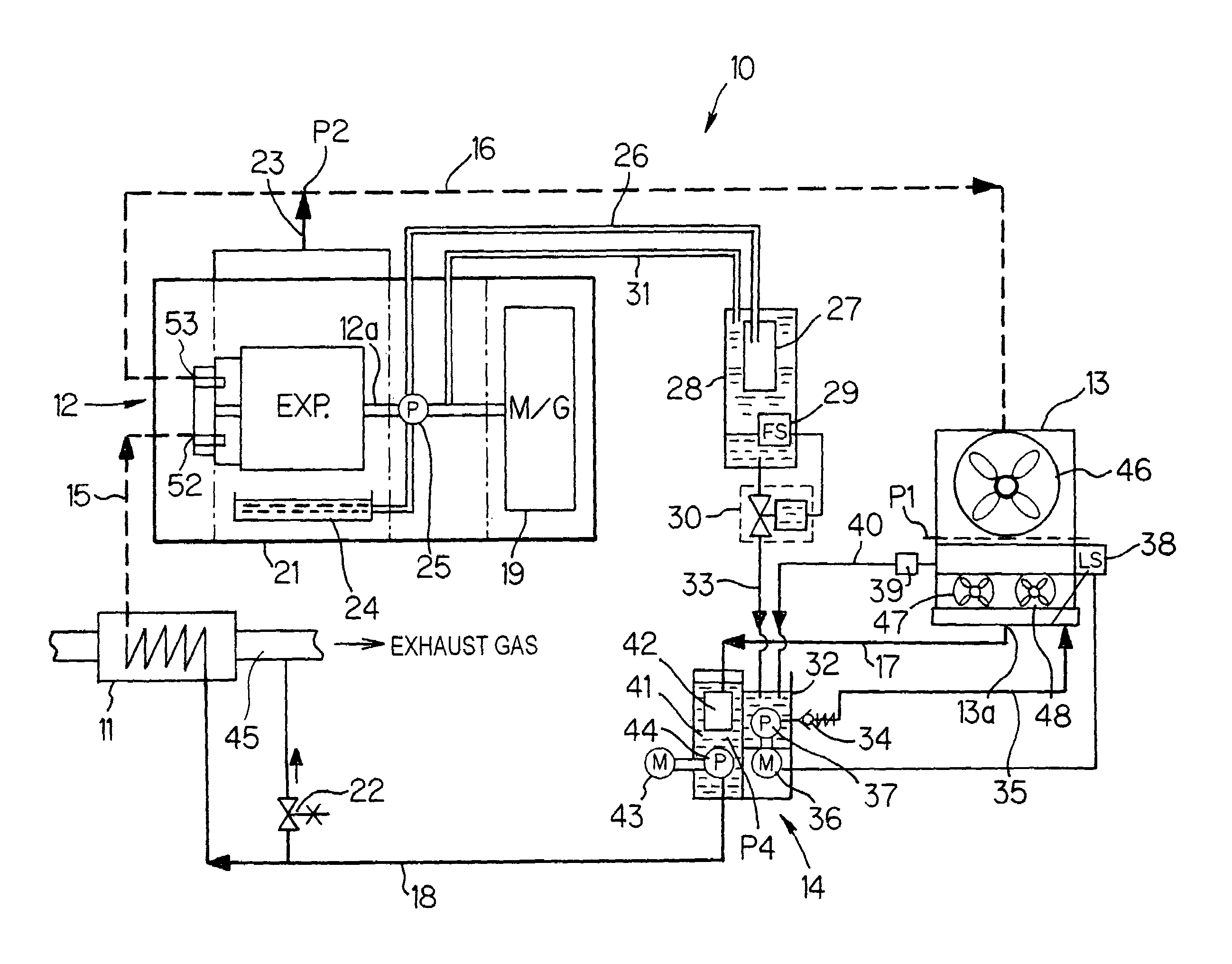
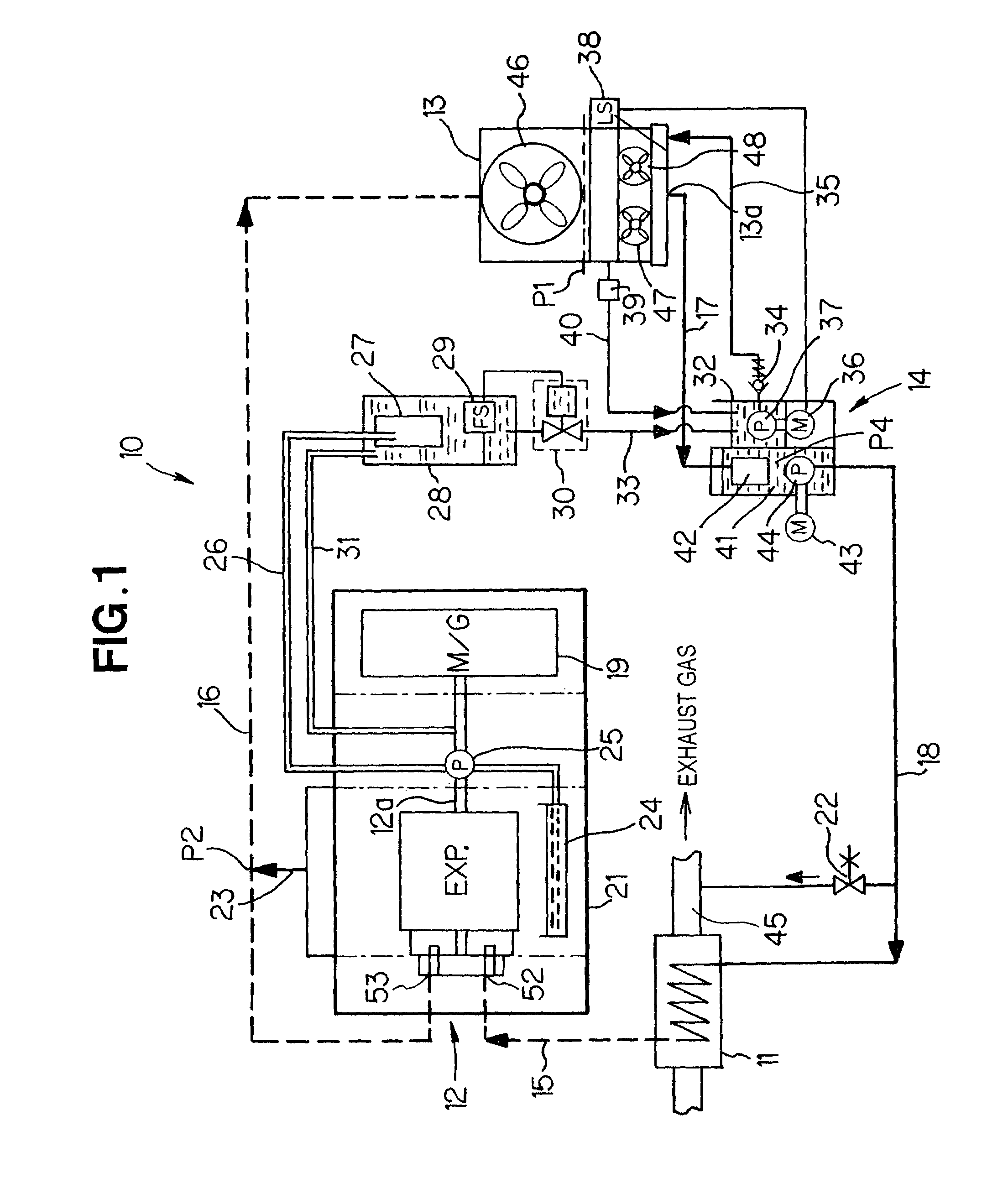
[0063]First, a description will be made about an example general setup of a Rankine cycle apparatus in accordance with an embodiment of the present invention, with reference to FIG. 1.

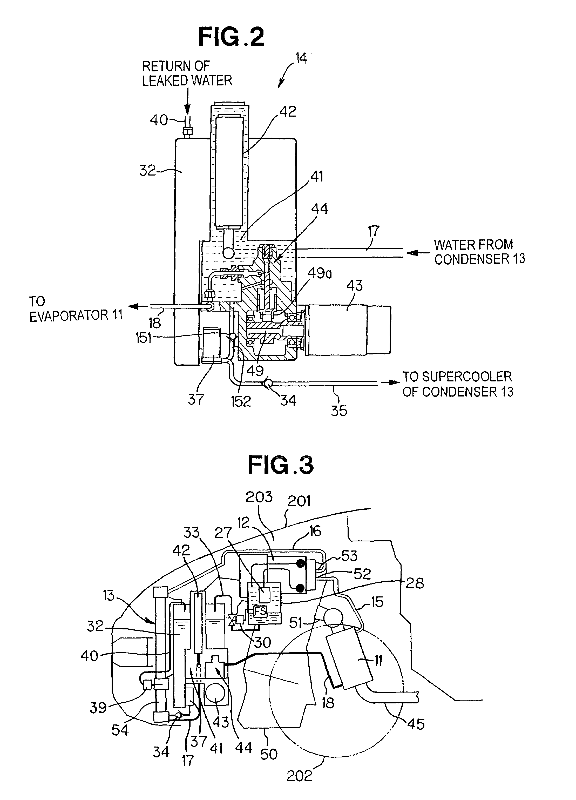
[0064]The Rankine cycle apparatus 10 includes an evaporator 11, an expander 12, a condenser 13, and a water supplying pump unit 14 provided with a supply pump.

[0065]The evaporator 11 and the expander 12 are interconnected via a pipe 15, and the expander 12 and the condenser 13 are interconnected via a pipe 16. Further, the condenser 13 and the water supplying pump unit 14 are interconnected via a pipe 17, and the water supplying pump unit 14 and the evaporator 11 are interconnected via a pipe 18. With such a piping structure, there is formed closed circulation circuitry (circulation system) through which a working medium is circulated within the Rankine cycle apparatus 10 in the gaseous or liquid phase. The working medium in the Rankine cycle apparatus 10 is in water (liquid) and water vapor (gaseous) ...


PUM

PropertyMeasurementUnit
temperatureaaaaaaaaaa
pressureaaaaaaaaaa

Abstract

Cooling control device for a condenser is provided which includes the condenser, a cooling device for cooling the condenser, and a control device for controlling the cooling device. The cooling device includes a first cooling fan for cooling a gaseous-phase portion of the condenser, and two second cooling fans for cooling a liquid-phase portion of the condenser independently of the first cooling fan. The control device also includes a pressure control section for optimally adjusting a pressure within the gaseous-phase portion, and a temperature control section for optimally adjusting a temperature within the liquid-phase portion. The pressure control section operates the first cooling fan, in accordance with a detected pressure within the gaseous-phase portion, to adjust the pressure within the gaseous-phase portion. The temperature control section operates the second cooling fans, in accordance with a detected temperature within the liquid-phase portion, to adjust the temperature within the liquid-phase portion.

Description

[0001]This Non-provisional application claims priority under 35 U.S.C. § 119(a) on Patent Application No(s). 2003-344492 and 2003-359865 filed in Japan on Oct. 2, 2003 and Oct. 20, 2003 respectively, the entire contents of which are hereby incorporated by reference.FIELD OF THE INVENTION[0002]The present invention relates generally to cooling control devices for condensers. More particularly, the present invention relates to an improved cooling control device which is applied to a condenser in a Rankine cycle apparatus that is used, for example, as a vehicle-mounted apparatus for converting exhaust heat energy of a vehicle-mounted engine into mechanical energy, and which controls a pressure within the condenser and temperature of condensed water within the condenser independently of each other.BACKGROUND OF THE INVENTION[0003]Rankine cycle apparatus have been known as systems for converting heat energy into mechanical work. The Rankine cycle apparatus include a structure for circula...

Claims


Application Information

Patent Timeline
Patent Type & Authority Patents(United States)
IPC IPC(8): F25B39/04F01K13/00F01K23/06F01K7/00F25B1/06B01D5/00F01K9/00F16T1/10
CPCB01D5/0093F16T1/10F01K23/065F01K9/00
Inventor TANIGUCHI, HIROYOSHIUDA, MAKOTO
Owner HONDA MOTOR CO LTD
Why Eureka
Try Eureka