Apparatus and method for percutaneous sealing of blood vessel punctures

a blood vessel and percutaneous sealing technology, applied in applications, veterinary instruments, catheter, etc., can solve the problems of external pressure devices, hematoma risk, impaired patient comfort and practitioner efficiency, etc., to facilitate possible reentry, reduce instrumentation change time, and adequate hemostatic pressure

Inactive Publication Date: 2007-02-13
BOSTON SCI CORP +11
View PDF223 Cites 157 Cited by
  • Summary
  • Abstract
  • Description
  • Claims
  • Application Information

AI Technical Summary

Benefits of technology

[0013]It is another object to employ an introducer instrument already in place at the access site to minimize instrumentation changing time, and to maintain access during an initial clotting period to facilitate possible reentry.
[0014]It is yet another object to maintain adequate hemostatic pressure on an adipose or fatty tissue layer above the puncture site in order to close the puncture naturally, to reduce the potential for pseudo-aneurysm formation, and to maintain such pressure by lightweight, non-labor intensive, mechanical means, thereby reducing patient discomfort.

Problems solved by technology

With externally applied manual pressure, both patient comfort and practitioner efficiency are impaired.
Additionally, a risk of hematoma exists since bleeding from the vessel may continue until sufficient clotting effects hemostasis.
Also, external pressure devices, such as femoral compression systems, may be unsuitable for patients with substantial amounts of subcutaneous adipose tissue, since the skin surface may be a considerable distance from the vascular puncture site, thereby rendering skin compression inaccurate and thus less effective.
Some likelihood exists of introducing the adhesive so employed disadvantageously into the bloodstream.
Unless pressure is applied, however, bleeding may occur around the plug into the subcutaneous tissue.
Such permanent placement of foreign material into the body may result in inflammation or scar formation in the long term.
Furthermore, many of the prior art devices rely on tactile sensation alone to indicate to the surgeon the proper placement of the puncture closing instrumentation, and may require upstream clamping of the blood vessel to reduce intraluminal pressure to atmospheric at the puncture site.
As the foregoing description of the prior art demonstrates, none of the heretofore proposed solutions fulfills the need for a relatively simple, non-cautery apparatus and method for subcutaneously applying pressure directly to the vicinity of the vessel puncture by means of a pressure element that is removed from the patient once sealing of the puncture is achieved.

Method used


Image

  • Apparatus and method for percutaneous sealing of blood vessel punctures
  • Apparatus and method for percutaneous sealing of blood vessel punctures
  • Apparatus and method for percutaneous sealing of blood vessel punctures

Examples


third embodiment

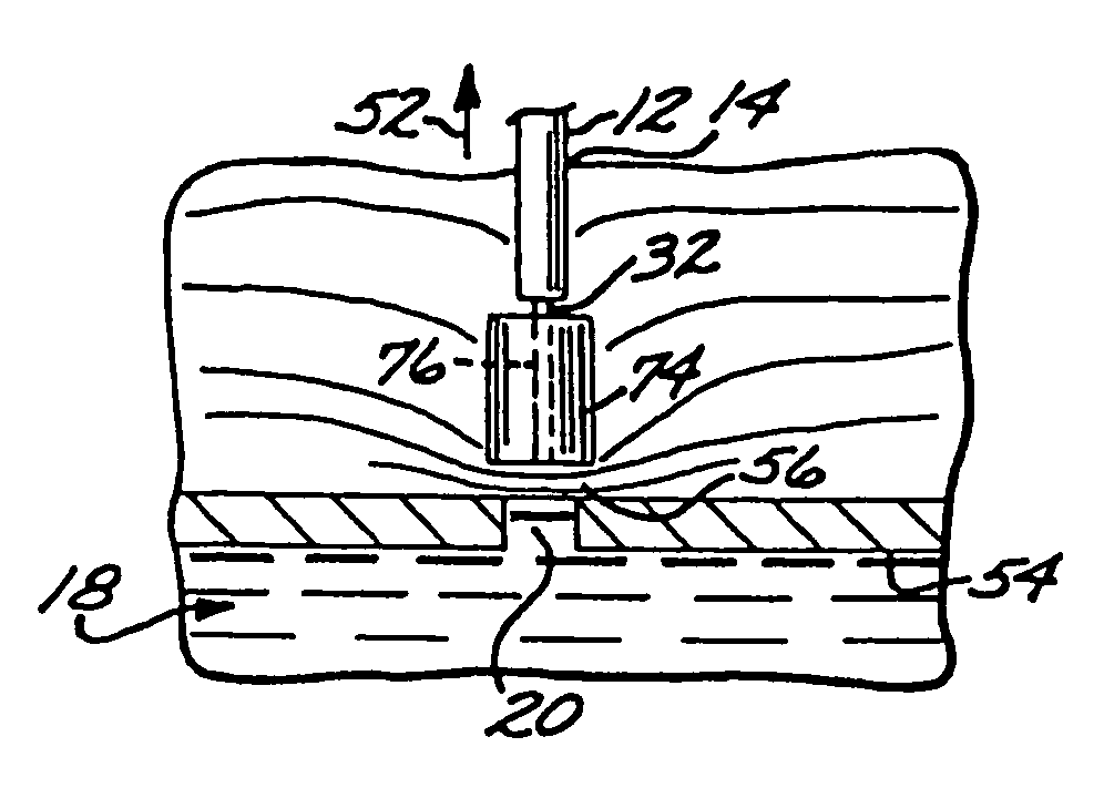
[0082]the method, following steps substantially identical to the above described procedures, involves the use of the compressible foam pad 74 shown in FIGS. 3 and 3A as the compression element at the distal end 34 of the catheter 32.

[0083]In this third embodiment, when the catheter 32 is in the preferred location as shown in FIG. 3, the introducer 12 is moved from its first or distal position to its second or proximal position (in the direction of the arrow 52) to uncover the foam pad 74, allowing it to expand, as illustrated in FIG. 3A. The expanded foam pad 74 exerts hemostatic pressure upon the fatty tissue layer 56, as described previously. The locator tube (not shown) passes through and is withdrawn from the pad channel 76 formed axially in the foam pad 74. If deemed desirable by the practitioner, a coagulant agent such as collagen, thrombin or protamine may be delivered to the vicinity of the puncture site through the pad channel 76 which communicates with the catheter axial l...

first embodiment

[0089]Still another method of the invention is illustrated in FIG. 5, wherein the apparatus 110 differs from the apparatus 10 in that the introducer 112 and the catheter 132 are not luer-locked together. FIG. 5 shows the position of the catheter 132 aligned with a visible marker band 57 on the locator tube 30, just as in the first embodiment described above. It will be readily understood that the method of this “luerless” apparatus 110 may be equally utilized with the guidewire 78 as with the locator tube 30 for the compression balloon embodiment of this invention.

[0090]When the preferred location of the expanded compression balloon 42 has been achieved as shown in FIG. 5, by applying either the guidewire or the locator tube methods previously explained, force must be applied from above to the compression balloon 42 to maintain hemostatic pressure on the fatty tissue layer 56. The practitioner advances the introducer 112 downward in the direction of the arrow 62 until the introducer...


PUM


Abstract

A device for promoting hemostasis in a blood vessel puncture is employed with an introducer that accesses the puncture through an incision. The introducer has an open distal end positionable at the puncture, an external portion with an open proximal end, and an axial channel therebetween. The device includes a hollow catheter, dimensioned to pass through the introducer channel, having a distal end to which is attached an expansible compression element, which may be an inflatable balloon, a collapsible prong assembly, or a resilient foam pad. The compression element is collapsed when the distal end of the catheter is enclosed within the introducer. When the catheter and the introducer are located at the desired distance from the puncture, the introducer is displaced axially relative to the catheter to expose the compression element to the subcutaneous tissue, whereupon the compression element is expanded.

Description

CROSS-REFERENCE TO RELATED APPLICATION[0001]This application is a divisional of application Ser. No. 09 / 365,674, filed on Aug. 2, 1999 now U.S. Pat. No. 6,371,974, which is divisional of application Ser. No. 08 / 888,851, filed Jul. 7, 1997, now U.S. Pat. No. 6,071,300, issued Jun. 6, 2000, which is a continuation-in-part of application Ser. No. 08 / 528,892, filed Sep. 15, 1996, now U.S. Pat. No. 5,645,566, issued Sep. 15, 1995, which is incorporated herein by reference in its entirety.FEDERALLY FUNDED REASEARCH OR DEVELOPMENT[0002]Not ApplicableBACKGROUND OF THE INVENTION[0003]The present invention relates generally to the field of apparatus and methods for sealing wounds in the blood vessels of humans or animals. More specifically, the invention relates to a guided vascular compression device for percutaneously sealing arterial or venous punctures subsequent to surgical procedures, by promoting in situ hemostasis.[0004]A large number of medical therapeutic and diagnostic procedures i...

Claims


Application Information

Patent Timeline
Patent Type & Authority Patents(United States)
IPC IPC(8): A61B17/08A61M25/00A61M29/00A61B17/00A61B17/12A61B17/34A61B19/00A61M25/04
CPCA61B17/0057A61M25/1011A61M25/04A61M25/0662A61B17/085A61B19/54A61B2017/00672A61B2017/00557A61B90/39
Inventor BRENNEMAN, RODNEYCRAGG, ANDREW H.
Owner BOSTON SCI CORP
Why Eureka
Try Eureka