Antenna device
a technology of antenna and antenna earth, which is applied in the structure of resonant antennas, antenna earthings, radiating elements, etc., can solve the problems of difficult impedance adjustment, inconvenient antenna installation, and inconvenient antenna installation, so as to reduce the occupied space of the antenna, reduce the lower limit frequency, and make the effect of small
- Summary
- Abstract
- Description
- Claims
- Application Information
AI Technical Summary
Benefits of technology
Problems solved by technology
Method used
Image

Examples
example 1 (
EXAMPLE)
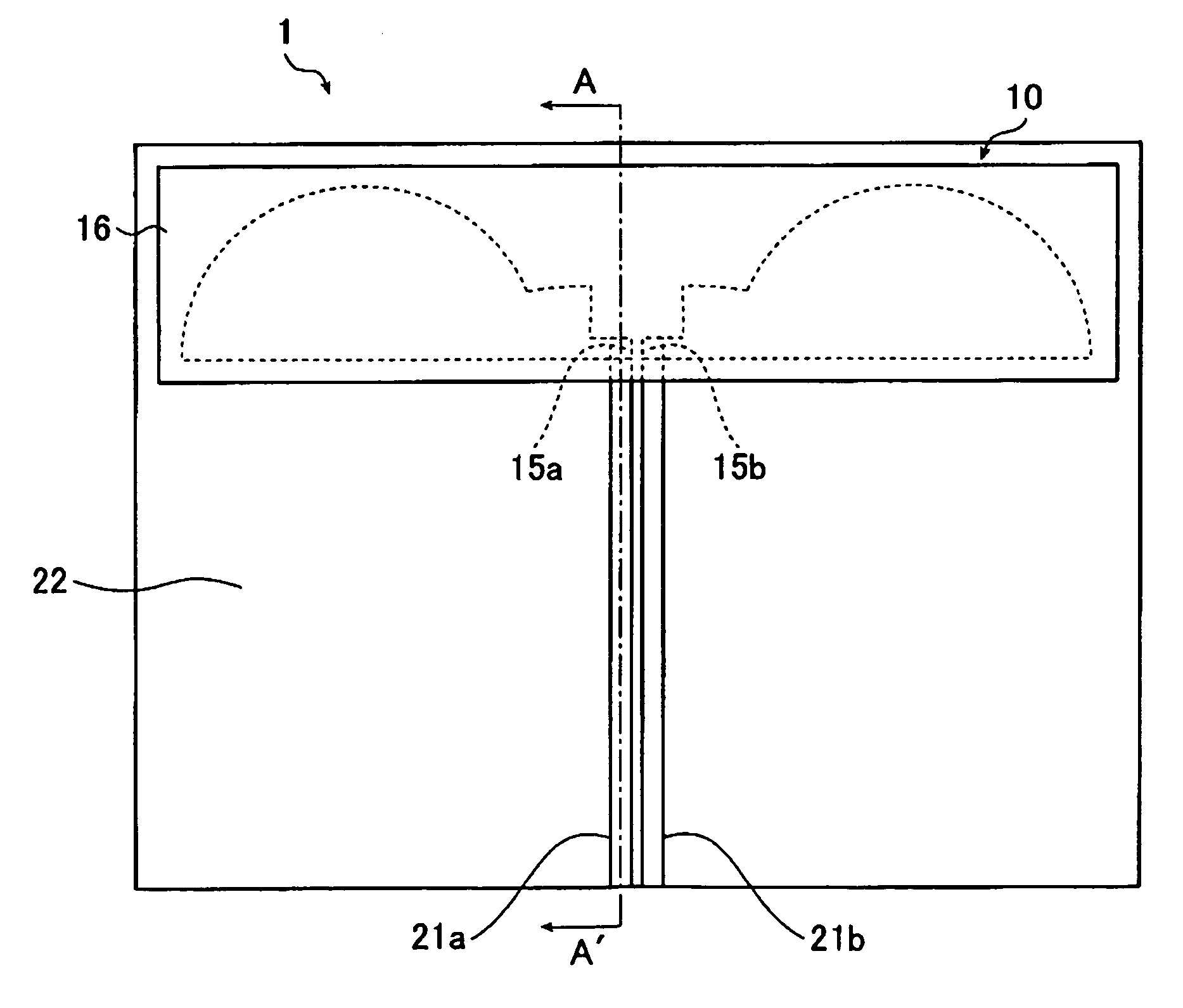
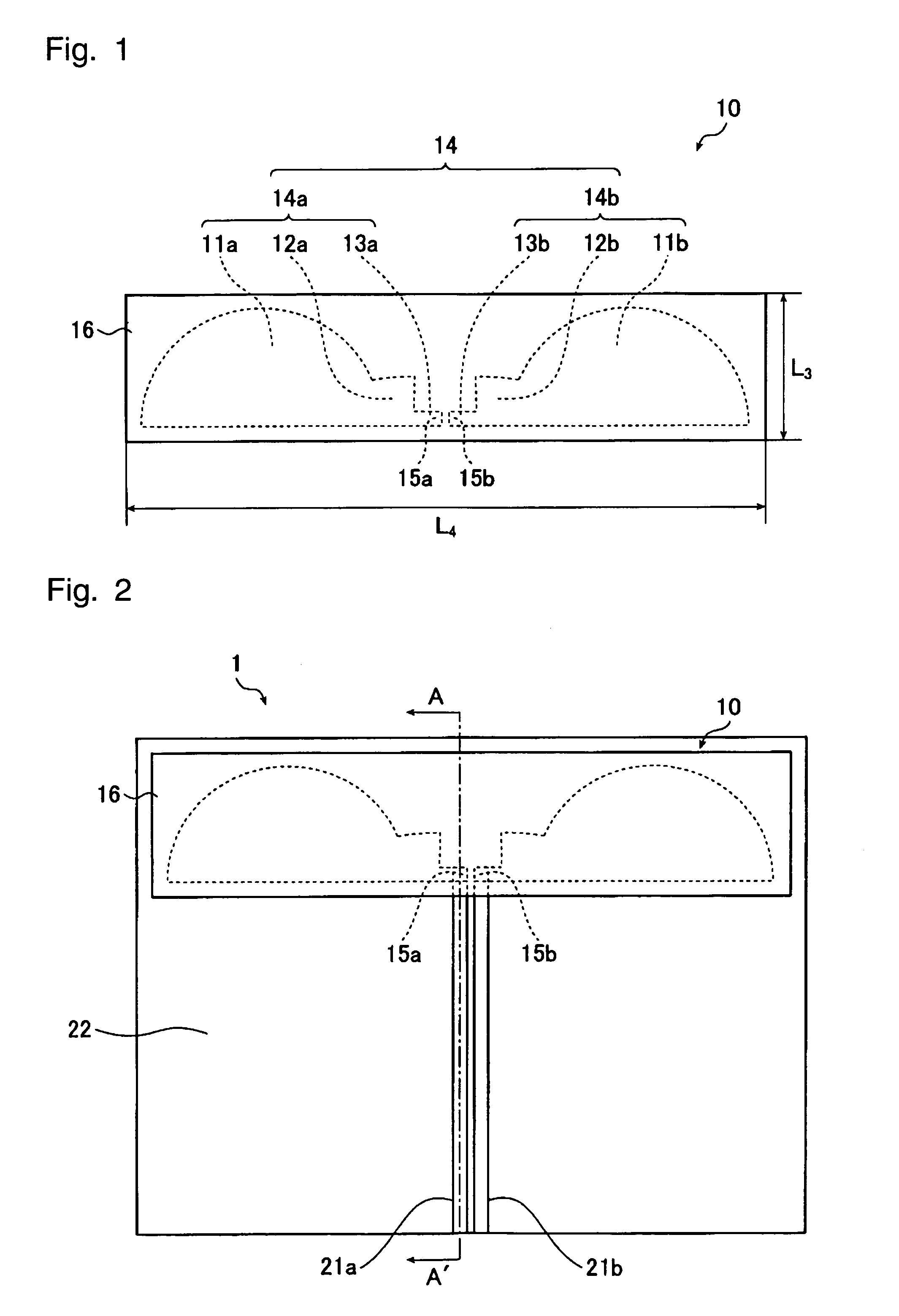
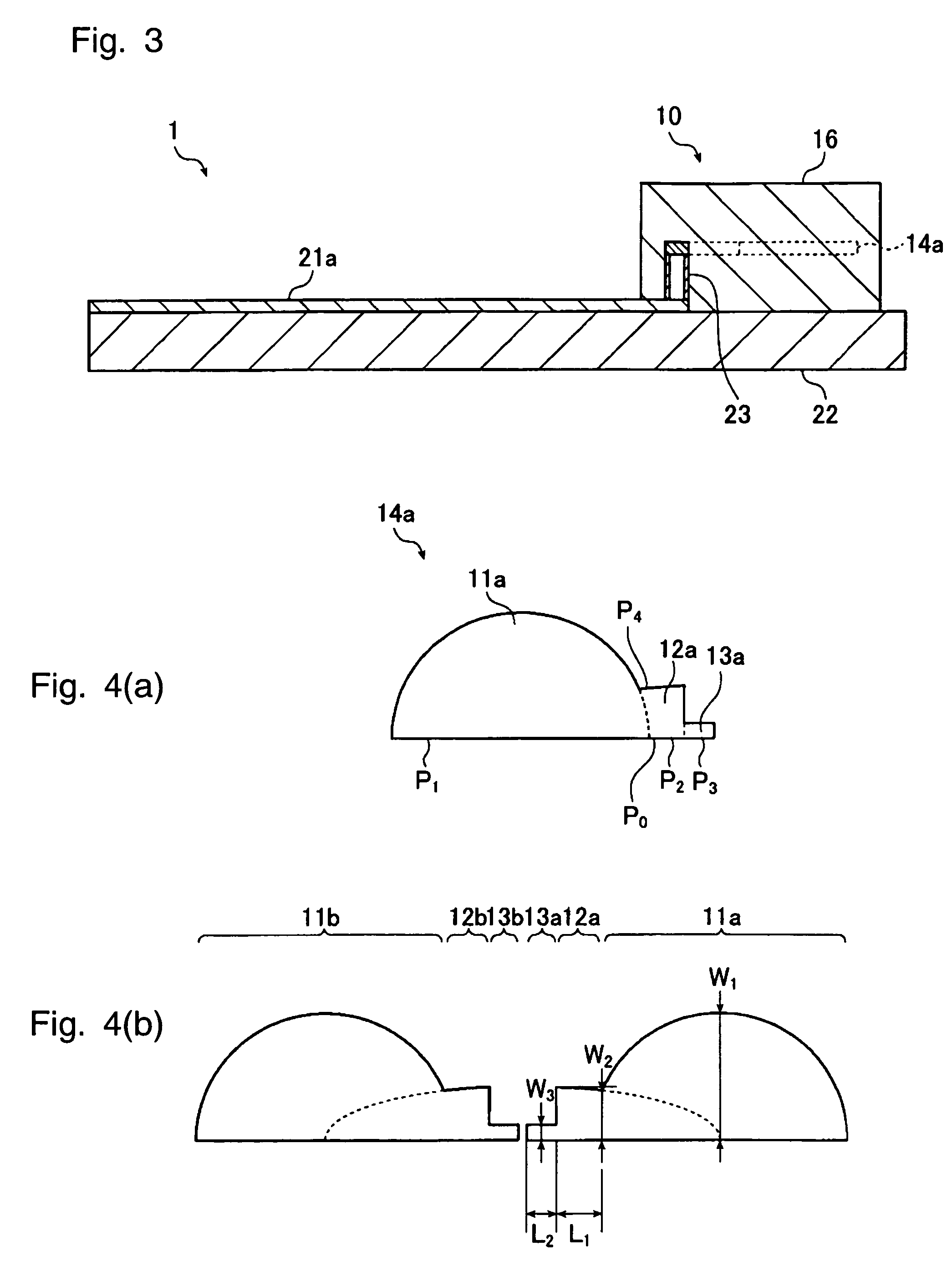
[0200]Example 1 is an example, which employs the antenna device 1 having the antenna body 10 shown in FIG. 1. Each of the first forming elements 11a and 11b is formed in a semi-circular shape. Each of the second forming elements 12a and 12b has a portion thereof formed in a ¼ oval shape. Each of the third forming elements 13a and 13b is formed in a band-like shape. The radiating conductor 14 is disposed at a substantially central portion in the thickness direction of the dielectric member 16. The antenna body 10 is mounted to a surface of the insulating substrate 22 as shown in FIG. 2. Dimensions of the respective forming elements and the dielectric member 16 are listed, along with dimensions in Example 3 to Example 7 stated later, in Table 1 below. References L3 and L4 designate the length in the vertical direction and the length in the horizontal direction shown in FIG. 1 and FIG. 8, respectively.
[0201]
TABLE 1Ex. 1Ex. 3Ex. 4Ex. 5Ex. 6Ex. 7FIG. 1FIG. 5FIG. 8FIG. 10(b)FIG. 1...
example 3 (
EXAMPLE)
[0211]Example 3 is an example, which employs the antenna device 51 having the antenna body 60 shown in FIGS. 5 and 6.
[0212]FIG. 19 is a graph showing a frequency characteristic of VSWR in Example 3. The frequency characteristic in Example 3 is found in accordance with electromagnetic field simulation by the FI (Finite-Integration) method. Dimensions of the respective forming elements and the dielectric member 66 are listed in Table 1 shown earlier.
[0213]Since the radiating conductor 64 has the same shape as the radiating conductor shown in FIG. 4(b), the same dimensional references (L3, L4 and L6) will be used in the following explanation. The vertical length and the horizontal length are the length in the vertical direction and the length in the horizontal direction in FIG. 5, respectively.
[0214]The dielectric member 66 comprises the first dielectric layer 66a, the second dielectric layer 66b and the third dielectric layer 66c defined below.
[0215]
Dielectric member 66First d...
example 4 (
EXAMPLE)
[0221]Example 4 is an example, which employs the antenna body 10 shown in FIG. 8. The first forming element 11a is formed in a semi-circular shape, and the first forming element 11b is formed in a combination of a ¼ circular shape and a square shape. Each of the second forming elements 12a and 12b is formed in a ¼ oval shape. Each of the third forming elements 13a and 13b is formed in a band-like shape. The radiating conductor 14 is disposed at a substantially central portion in the thickness direction of the dielectric member 16. The antenna body 10 is mounted to a surface of an insulating substrate (not shown) having a ground conductor so that the antenna body 10 is apart from the ground conductor (not shown) by 1 mm in the vertical direction. The dielectric member 16 comprises a first dielectric material sandwiched between second and third dielectric materials, the first dielectric material having a relative dielectric constant of 20, and the second and third dielectric m...
PUM
 Abstract
Description
Claims
Application Information
 - R&D
- Intellectual Property
- Life Sciences
- Materials
- Tech Scout
- Unparalleled Data Quality
- Higher Quality Content
- 60% Fewer Hallucinations
Browse by: Latest US Patents, China's latest patents, Technical Efficacy Thesaurus, Application Domain, Technology Topic, Popular Technical Reports.
© 2025 PatSnap. All rights reserved.Legal|Privacy policy|Modern Slavery Act Transparency Statement|Sitemap|About US| Contact US: help@patsnap.com