System for permanent electrode placement utilizing microelectrode recording methods

a recording system and electrode technology, applied in the field of medical leads and microelectrode recording systems, can solve the problems of intracranial bleeding, puncturing the vessel, and none of these companies manufacture their own microelectrodes, and achieve the effects of reducing critical operating time, preventing tangling with the microelectrode, and increasing the accuracy of placemen

Inactive Publication Date:
View PDF19 Cites 160 Cited by
  • Summary
  • Abstract
  • Description
  • Claims
  • Application Information

AI Technical Summary

Benefits of technology

[0026]In each system embodiment, the stimulation lead may contain a conductor coil that defines an inner, axial lumen. The stimulation lead may have, at its proximal end, a connector portion that is angled from the remainder of the lead. This connector angle helps to divert the lead connection away from the remainder of the lead and prevents tangling with the microelectrode. The stimulation lead may have an array of electrodes placed on the distal portion of the lead in an in-line placement.
[0027]In another aspect of the invention, there is provided a method of placing a DBS stimulating lead and inserting a microelectrode that eliminates procedural steps and thus reduces critical operating time. Each embodiment of the method commonly shares the feature that the microelectrode may be inserted and fully passed through the lumen of the stimulating lead, commencing at the lead's distal or proximal end. The embodiments of the method include: (1) placing the microelectrode into tissue first and placing the DBS stimulating lead over the microelectrode, (2) concurrently placing the microelectrode / DBS stimulating lead into a target tissue, or (3) placing the DBS stimulating lead into the target tissue first and then inserting the microelectrode into the lumen of the DBS stimulating lead. The flexibility of the various method embodiments can increase the accuracy of placing a DBS lead and microelectrode near the target neurons and thereby improve treatment efficacy and conserve the device battery life.

Problems solved by technology

None of these companies manufacture their own microelectrodes, although they may provide a microelectrode as part of the MER system package.
The set-up time may be proportionately cut, since the chance of locating a good stimulation site theoretically increases by five times. A disadvantage presented is that because the microelectrodes are placed relatively close to each other, two of these electrodes could “capture” a blood vessel between the electrodes, puncturing the vessel and possibly leading to intracranial bleeding.
Other neurosurgeons only record from one recording tract, which cuts surgery duration, but which may not locate an optimal stimulation site.
Without optimal electrode placement, the DBS lead may need to be stimulated at higher currents, which can cause the device battery to be drained more quickly.
In addition, use of higher currents can increase the risk of undesirable side effects such as dysarthria (slurred speech) and abulia (an abnormal inability to make decisions or to act).
These conventional surgical procedures are far from ideal.
The number of steps lengthen the surgical procedure and increase the risk for post-operative infection.
In addition, having to retrace the microelectrode pathway and the macroelectrode pathway to place the DBS lead substantially increases the chances for misalignment and misplacement because each of these steps require use of a separate introduction cannula.
Morever, the use of at least three cannulas in the procedure can increase surgical duration and operative risk, simply from the number of objects inserted into the brain.
In addition, retracing the pathway of the microelectrode and the macroelectrode as preliminary steps to placing the permanent DBS lead is fraught with misalignment / misplacement problems because the introduction cannulas may not trace the exact pathways desired.

Method used


Image

  • System for permanent electrode placement utilizing microelectrode recording methods
  • System for permanent electrode placement utilizing microelectrode recording methods
  • System for permanent electrode placement utilizing microelectrode recording methods

Examples


example 1

Microelectrode Placed Before the DBS Lead

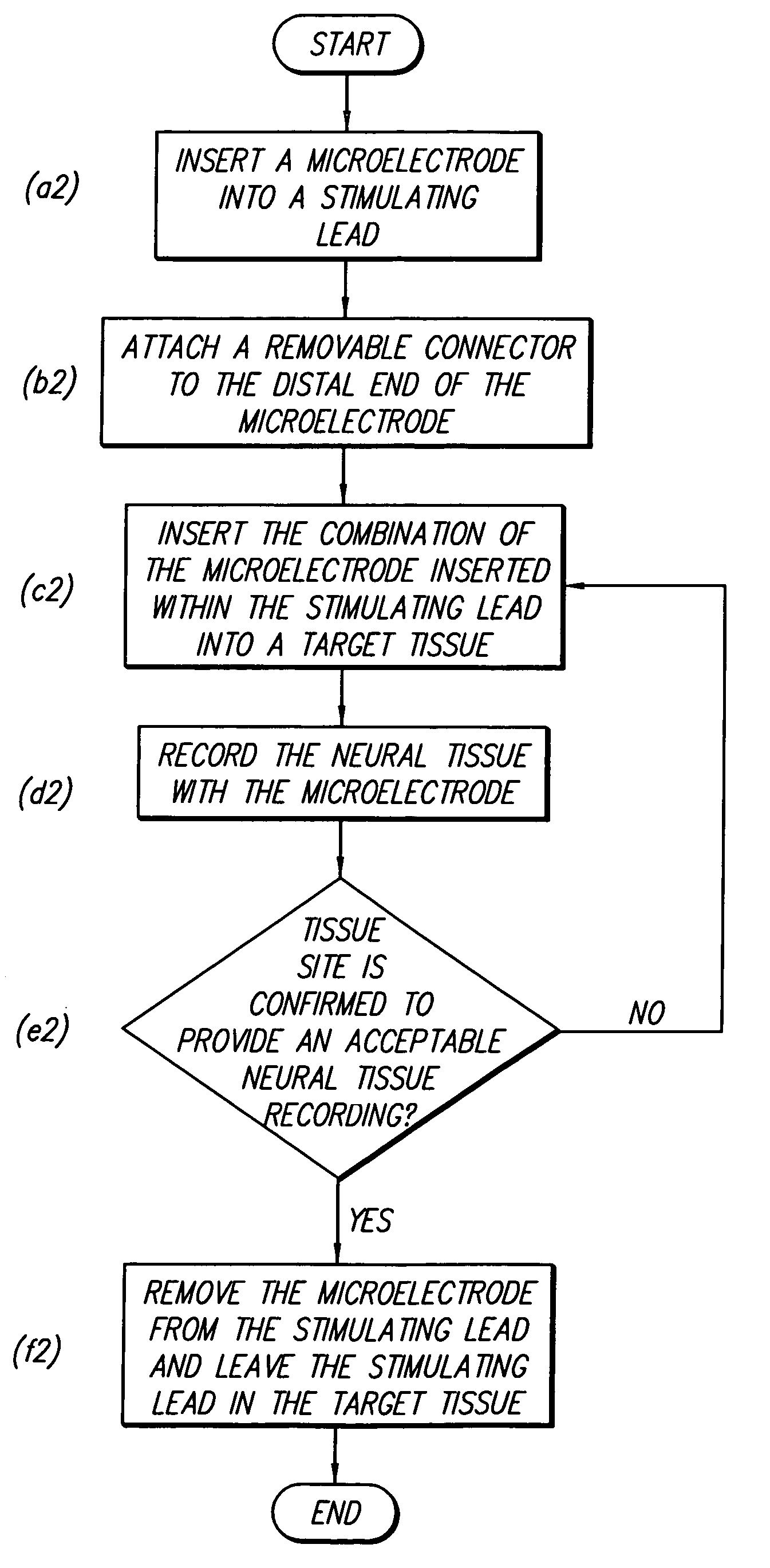
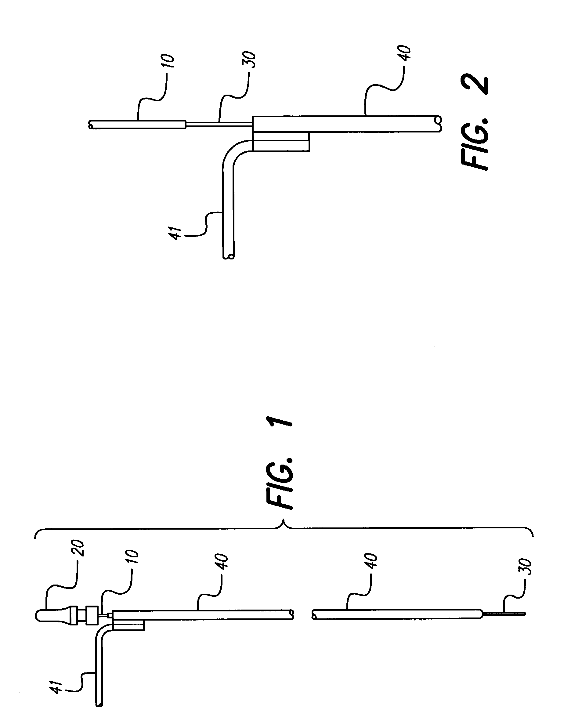
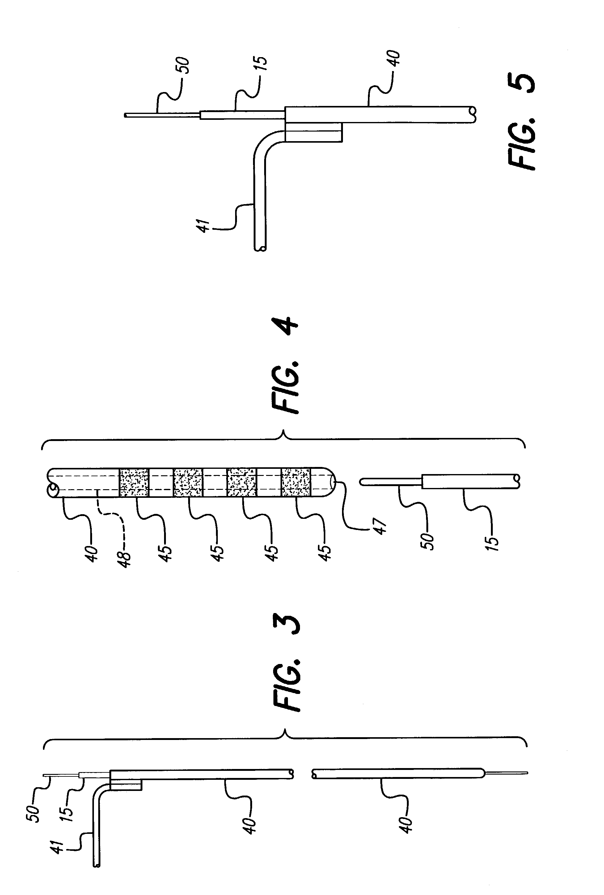
[0093]An introduction cannula is inserted into the brain. The microelectrode is inserted through the cannula with the connector attached and cell recording is performed. When a promising tissue site is found, the connector is detached from the microelectrode and the Advanced Bionics DBS lead is inserted over the proximal end of the microelectrode and advanced into the brain until an electrode on the DBS lead is precisely at the located tissue site. Macrostimulation is performed with the DBS lead. If a physiologically acceptable response is obtained, then the microelectrode may be withdrawn and the DBS lead may be fixed for permanent implantation. If the physiological response is not acceptable, then the DBS lead and or microelectrode can be repositioned together or separately to locate a suitable tissue site.

example 2

Microelectrode Placed Concurrently with DBS Lead

[0094]An introduction cannula is inserted into the brain. The microelectrode / Advanced Bionics DBS lead combination is inserted through the cannula with the connector attached to the microelectrode. The microelectrode is advanced slightly out of the distal end of the DBS lead and cell recording is performed. When a promising tissue site is found, the DBS lead is advanced over the distal end of the microelectrode until the electrodes on the DBS lead is precisely at the located tissue site. Macrostimulation is performed with the lead. If a physiologically acceptable response results, then the microelectrode may be withdrawn and the DBS lead may be fixed for permanent implantation. If the physiological response is not acceptable, then the DBS lead and or microelectrode can be repositioned such that microelectrode recording and / or macrostimulation can be performed until the DBS lead is properly positioned.

example 3

Microelectrode Placed after the DBS Lead

[0095]An introduction cannula is inserted into the brain. An Advanced Bionics DBS lead has been inserted into the brain but the macrostimulation does not yield the desired physiological response. There is no microelectrode inserted inside the DBS lead. A microelectrode is then inserted through the DBS lead, and a microrecording is performed to locate a suitable tissue site. The lead position (depth) is then adjusted to coincide with the located site.


PUM


Abstract

A lead stimulation/recording system is provided, which is a combination of a permanent DBS stimulating lead and a recording microelectrode. The DBS lead has a lumen extending from the proximal to the distal end of the lead, the lumen having an opening on each end of the lead. The microelectrode is configured and dimensioned to be insertable into the DBS lead from either the distal or proximal opening of the DBS lead, thereby permitting the microelectrode to be placed before, concurrently with, or after placement of the DBS lead. In addition, the system may be used with known microelectrode recording systems and methods of inserting the electrodes, such as the five-at-a-time method, the dual-microdrive method, or the single microdrive method.

Description

[0001]The present application is a Continuation-In-Part of U.S. Pat. No. 7,033,326, issued Apr. 25, 2006, which claims the benefit of U.S. Provisional Patent Application Ser. No. 60 / 258,767, filed Dec. 29, 2000. Both U.S. Pat. No. 7,033,326 and the provisional application are incorporated herein by reference.[0002]In addition, the present application claims the benefit of U.S. Provisional Patent Application Ser. No. 60 / 388,871, filed 13 Jun. 2002, which application is incorporated herein by reference.BACKGROUND OF THE INVENTION[0003]The present invention relates to medical leads and microelectrode recording systems used for functional neurosurgical procedures.[0004]Deep brain stimulation (DBS) is being increasingly accepted as a viable treatment modality. In particular DBS applied to the thalamus for treatment of tremor was approved by the FDA in 1997. Subsequently, other diseases, such as Parkinson's Disease, dystonia, and chronic pain, among others, have been identified as candida...

Claims


Application Information

Patent Timeline
Patent Type & Authority Patents(United States)
IPC IPC(8): A61N1/05
CPCA61B5/04001A61N1/0539A61N1/0529Y10S439/909A61B5/24
Inventor PIANCA, ANNE M
Why Eureka
Try Eureka