High intensity ablation device

a high-intensity ablation and device technology, applied in the field of surgical instruments, can solve the problem that instruments may not be able to guarantee transmural lesion, and achieve the effect of enhancing performan

Active Publication Date: 2007-02-20
ETHICON INC
View PDF21 Cites 585 Cited by
  • Summary
  • Abstract
  • Description
  • Claims
  • Application Information

AI Technical Summary

Benefits of technology

[0008]Since the myocardial tissue is about 3–6 mm thick and is significantly thicker than the venous wall, the lesions need to be transmural in order for the lesion to be effective in creating a line of electrical block to treat AF. Typical existing instruments may not be able to guarantee a transmural lesion and / or may compromise tissue structure and / or form coagulum / thrombus. The present invention discloses a system to overcome the limitations of the prior art by providing an instrument whose performance is enhanced by clamping. The present invention further overcomes the limitations of the prior art by allowing the conduction blocks to be created from either the epicardial or the endocardial surface or both, and can be performed on a beating heart or an externally perfused heart.

Problems solved by technology

Typical existing instruments may not be able to guarantee a transmural lesion and / or may compromise tissue structure and / or form coagulum / thrombus.

Method used


Image

  • High intensity ablation device
  • High intensity ablation device
  • High intensity ablation device

Examples


first embodiment

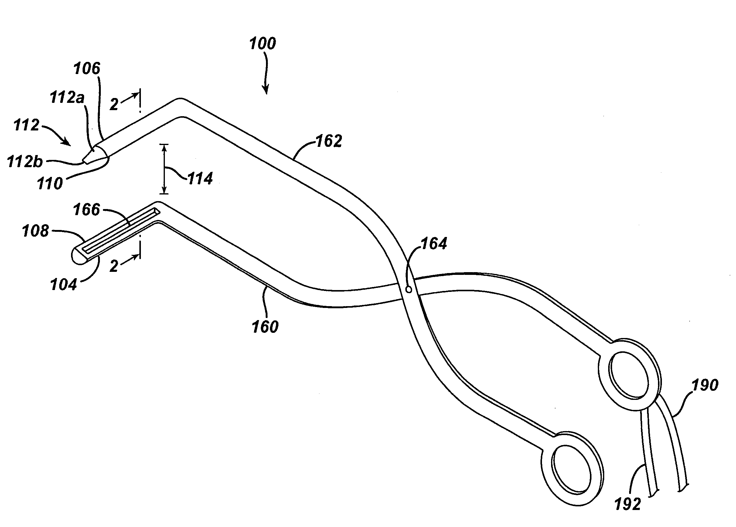
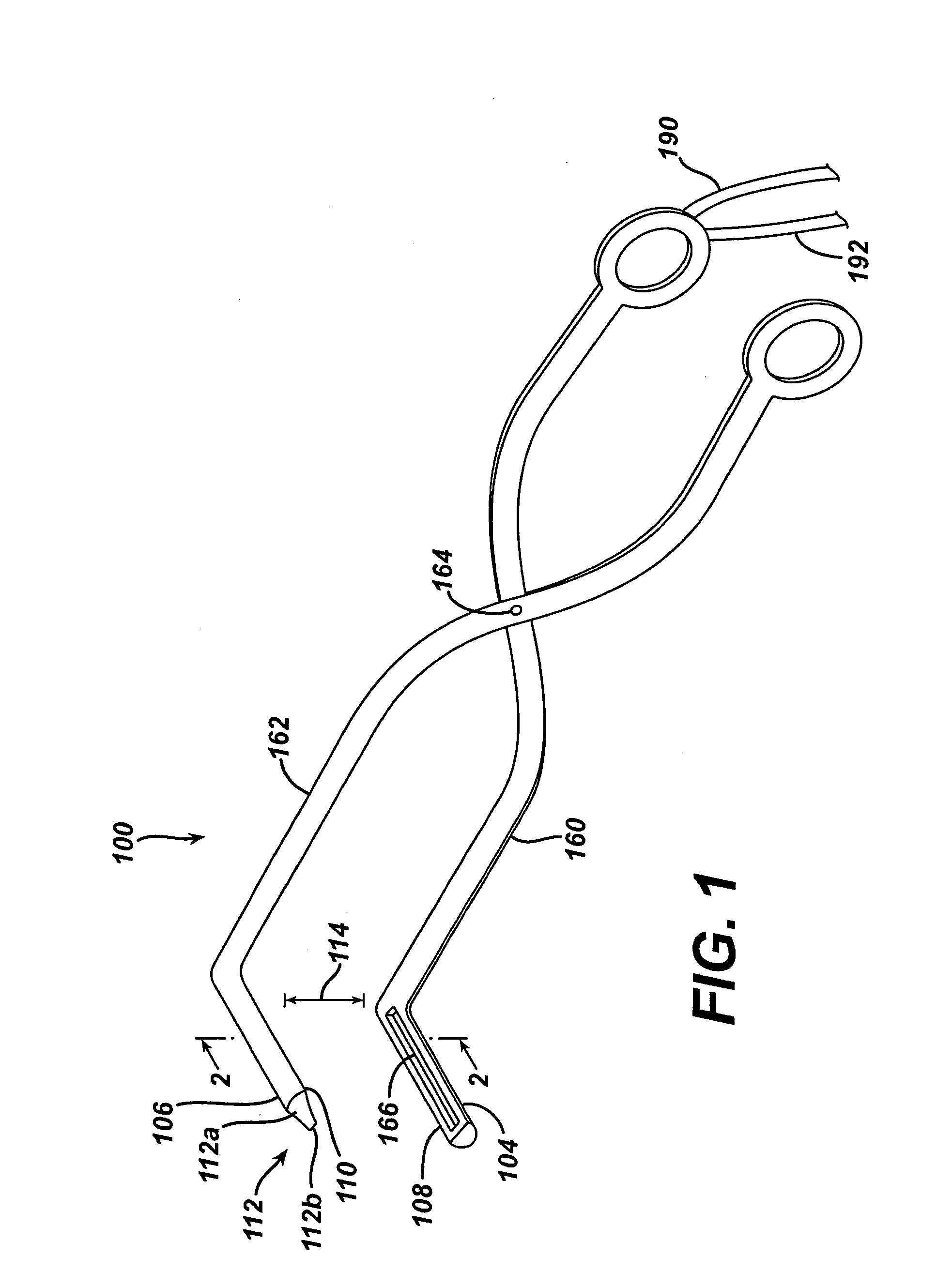
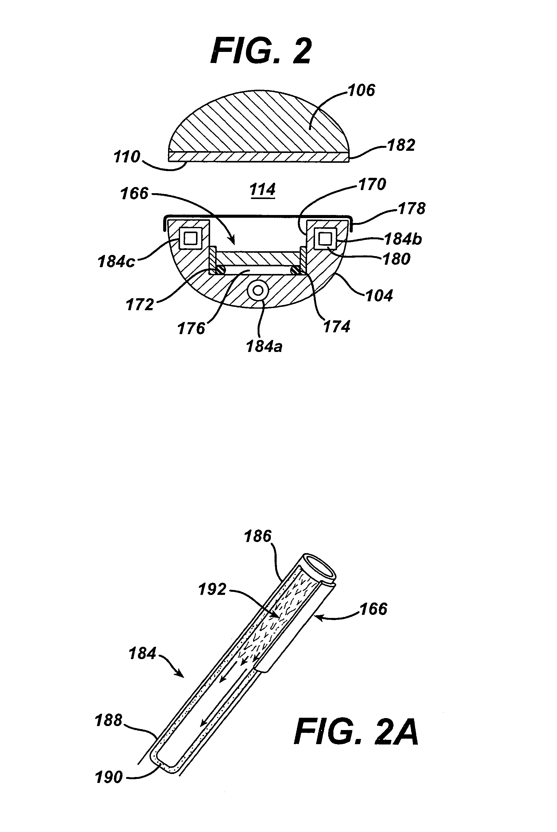
[0028]Referring now to FIG. 1, in a first embodiment the instrument, generally 100, generally has a distal end 102 having first elongated jaw 104 and second elongated jaw 106. Each of the first and second elongated jaws 104, 106 has a respective first ablation surface 108 and second ablation surface 110. As will be described in more detail, an ablation surface can comprise a surface adjacent or part of a source of ablative energy, or a surface reflecting incident ablative energy. At least one of the first and second elongated jaws 104, 106 may include a pointed distal tip 112 useful for piercing tissue. Preferably, the pointed distal tip 112 comprises a tapered surface 112a terminating in a sharp leading edge 112b. Those skilled in the art will appreciate that the pointed distal tip 112 may be configured in many ways without departing from the scope or spirit of the present invention. For example, the pointed distal tip 112 may be conical and terminate in a point or have two tapered...

second embodiment

[0044]an ablative clamp, generally 200, is shown in FIGS. 3–5. Clamp 200 has a first elongated jaw 204 and a second elongated jaw 206. As seen in each of FIGS. 3–5, the first and second elongated jaws 204, 206 are curved along their length. The first and second elongated jaws 204, 206 are mounted on the distal end of a shaft 261. In this embodiment, the shaft represent a flexible malleable shaft, a preferred embodiment of which is disclosed in U.S. patent application Ser. No. 10 / 736,199, filed 15 Dec. 2003, the complete disclosure of which is hereby incorporated by reference. Shaft 261 may also be a rigid shaft, steerable / flexible shaft, or other suitable configuration as is known in the art. In this embodiment, the first and second elongated jaws are articulated to be parallel to each other, for example by an actuating cable or shaft in, on or near shaft 261.

[0045]Referring now to FIG. 5, the ablative clamp 200 is shown in cross-section. First elongated jaw 204 has an ultrasonic tr...


PUM


Abstract

An apparatus for ablating tissue, the apparatus having first and second opposing jaws operative to compress tissue to be allayed therebetween, the first jaw having a first ablation surface directing ablative energy into the tissue and the second jaw having a second ablation surface reflecting incident ablative energy into the tissue. The ablative energy may be ultrasonic, microwave, cryoablation, radio-frequency, photodynamic, laser, and cautery energy. The instrument may also have a pointed tip for piercing tissue, allowing the instrument to clamp the tissue wall of a hollow organ before ablation. Alternately, the instrument may clamp two or more tissue layers of a hollow organ without piercing prior to clamping an ablation.

Description

BACKGROUND OF THE INVENTION[0001]1. Field of Invention[0002]The present invention relates generally to surgical instruments, and more particularly, to a high intensity ablation device to create linear lesions in tissue, such as a surface of the heart.[0003]2. Description of Related Art[0004]Atrial fibrillation (AF) is a commonly occurring disorder that causes the atria to beat erratically. This condition can cause thromobogenesis and strokes. It can be treated pharmacologically, but many patients are not responsive to these therapies. It is generally accepted that creating lesions in the atria that create conduction blocks are a good way to do this.[0005]There have been a number of procedures developed to treat atrial fibrillation. These include the surgical MAZE procedure, where the heart of the patient is stopped and the left and right atria are opened. The atrium is then divided into pieces and sewn back together. It is presumed that the scars that form from these cuts effectivel...

Claims


Application Information

Patent Timeline
Patent Type & Authority Patents(United States)
IPC IPC(8): A61B18/18A61B18/04
CPCA61B17/320092A61N7/02A61B18/1447A61B18/1815A61B18/20A61B2018/00023A61B2018/00029A61B2018/00357A61B2018/00363A61B2018/00577A61B2018/0225A61B2018/145A61B2018/00291A61B2017/320094A61B2017/320095
Inventor PENDEKANTI, RAJESHPODANY, VACLAV O.
Owner ETHICON INC
Why Eureka
Try Eureka