Method and apparatus for magnetoresistive monitoring of analytes in flow streams

a flow stream and magnetoresistive technology, applied in the field of microfluidics, can solve the problems of bulky detectors and labels, potential radiohazards, and expensive detectors, and achieve the effects of reducing the number of detectors, and improving the detection efficiency

Inactive Publication Date: 2007-02-20
IOWA STATE UNIV RES FOUND +1
View PDF10 Cites 50 Cited by
  • Summary
  • Abstract
  • Description
  • Claims
  • Application Information

AI Technical Summary

Benefits of technology

[0008]In that regard it is an object to utilize the high sensitivity of the giant magnetoresistive

Problems solved by technology

Radioactive labels are useful in that they offer a low level of detection, but they require expensive detectors, present a potential radiohazard, and can be unstable.
Light emitting labels, though sensitive, require specialized detectors and labels, which are bulky and/or expensive.
In that particular example, the requirements of parasite filtration, concentration, separation, and monitoring require bulky instrumentation and manual operation.
Insofar as a

Method used


Image

  • Method and apparatus for magnetoresistive monitoring of analytes in flow streams
  • Method and apparatus for magnetoresistive monitoring of analytes in flow streams
  • Method and apparatus for magnetoresistive monitoring of analytes in flow streams

Examples


Embodiment Construction

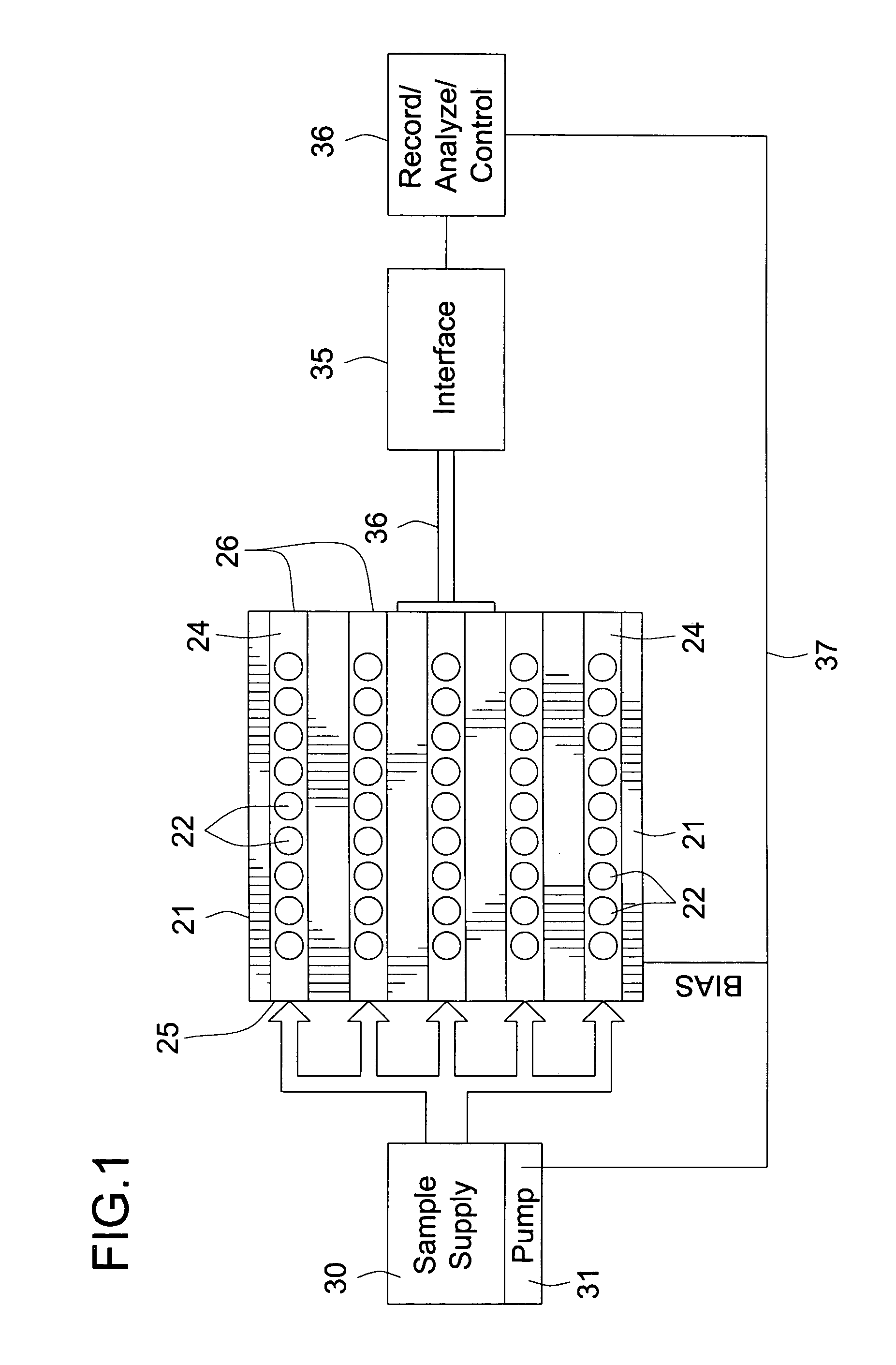
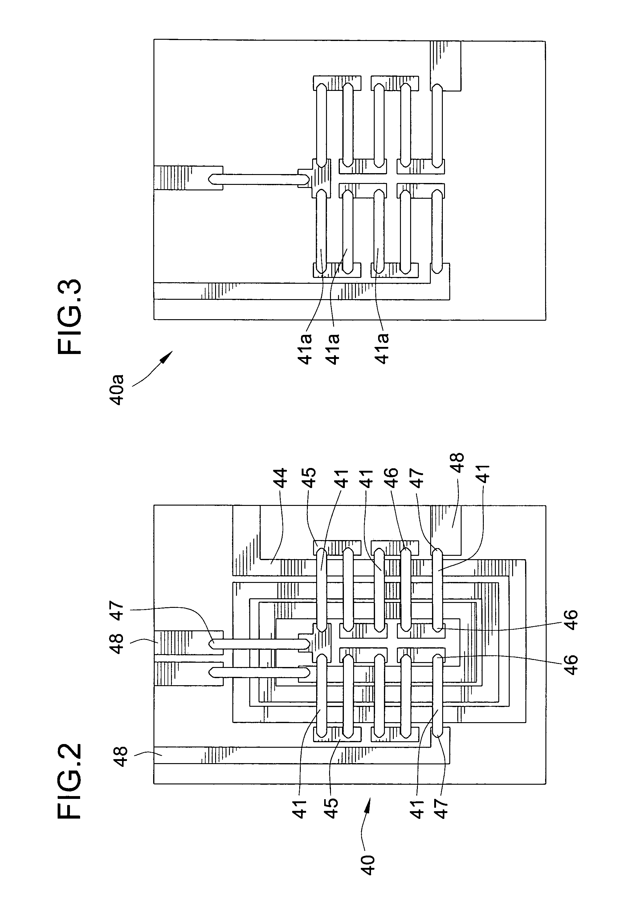
[0029]Turning now to the drawings, FIG. 1 shows the general scheme of a detection system and method in accordance with the present invention. The detector assembly itself is a giant magnetoresistive sensor 21 GMR, and comprises an integrated circuit having a plurality of sensor elements formed in an array across its planar surface. Individual sensor elements are shown at 22, for example.

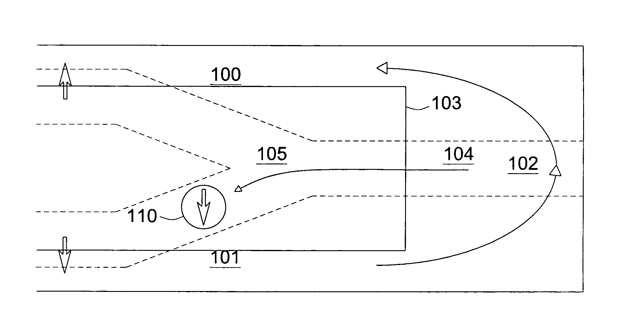
[0030]In contrast to prior sensors that utilize techniques to cause the analyte to bind at the sensor cell locations 22, the sensor 21 of the present invention includes structure for causing the analyte fluid to flow across the face of the sensor in proximity to the cells 22. In the illustrated embodiment, that flow structure is illustrated by a plurality of microfluidic channels 24, having an inlet side 25 and a outlet side 26. Although not illustrated, a sample collection container would typically by included after the outlet side 26. The microfluidic channels 24 provide microminiature conduits for...


PUM

PropertyMeasurementUnit
Angleaaaaaaaaaa
Timeaaaaaaaaaa
Concentrationaaaaaaaaaa

Abstract

Method and apparatus for manipulating and monitoring analyte flowing in fluid streams. A giant magnetoresistive sensor has an array of sensing elements that produce electrical output signals which vary in dependence on changes in the magnetic field proximate the sensing elements. The analyte is included in a stream, such that the stream has a magnetic property which is dependent on the concentration and distribution on the analyte therein. The stream is flowed past the giant magnetoresistive sensor and in sufficiently close proximity to cause the magnetic properties of the stream to produce electrical output signals. The electrical output signals are monitored as an indicator of analyte concentration or distribution in the stream flowing past the GMR sensor. Changes in the magnetic field produced by the background stream are introduced by analyte molecules, whose presence in the flow past the GMR will effect the output reading.

Description

CROSS-REFERENCE TO RELATED PATENT APPLICATIONS[0001]This patent application is a divisional of U.S. patent application Ser. No. 10 / 017,467, filed Dec. 13, 2001, now U.S. Pat. No. 6,736,978, which claims the benefit of U.S. Provisional Patent Application No. 60 / 255,211, filed Dec. 13, 2000.STATEMENT REGARDING FEDERALLY SPONSORED RESEARCH AND DEVELOPMENT[0002]This invention was developed with governmental assistance under NSF Contract No. BES-0088241 and NSF Contract No. DMI-9961163. The Government may have certain rights in this invention.FIELD OF THE INVENTION[0003]This invention relates to microfluidics, to on-chip manipulation of analytes in fluid streams, and to monitoring for the presence and concentration of analytes in fluid (i.e., liquid or gas) streams.BACKGROUND OF THE INVENTION[0004]For low levels of detection, bioassays usually require labels or tags which connect the recognition process to a transduction mechanism. Such labels include radioactive compounds, enzymes and l...

Claims


Application Information

Patent Timeline
IPC IPC(8): B03C1/00G01N33/553G01N33/543
CPCG01F1/708G01N33/54333Y10S436/806
Inventor PORTER, MARC DNI, JINGDAWSON, G BRENTSHINAR, RUTHLIPERT, ROBERT JGRANGER, MICHAEL CTONDRA, MARK
Owner IOWA STATE UNIV RES FOUND
Why Eureka
Try Eureka