Heat treatment apparatus

a heat treatment apparatus and heat treatment technology, applied in the field of heat treatment apparatus and heat treatment method, can solve the problems of requiring a more complicated and larger-scale apparatus structure, affecting the efficiency of heat treatment equipment, and reducing the degree of freedom of apparatus arrangement, so as to simplify the configuration of the magnetic field generating device and save weight and height of the apparatus

Active Publication Date: 2007-02-20
TOKYO ELECTRON LTD
View PDF15 Cites 15 Cited by
  • Summary
  • Abstract
  • Description
  • Claims
  • Application Information

AI Technical Summary

Benefits of technology

[0020]An object of the present invention is therefore to provide a heat treatment apparatus which permits simplifying the configuration of the magnetic field generating device by using a compact solenoid type magnet (air-core coil), thereby permitting saving of the weight and height of the apparatus, reducing the installation area to the same order as the conventional one, achieving an apparatus installable in a usual clean room, and treating a large quantity of large-sized objects of treatment as compared with conventional art.
[0027]According to further another embodiment of the present invention, the heating device is an electric heater having a dual-wire structure, so that the magnetic field generated from the electric heater does not inhibit the magnetic field generated by the magnetic field generating device.

Problems solved by technology

In order to prevent generation of dust from the holder supporting unit 3B and the moving device, therefore, it is necessary to extensively make efforts to eliminate dust from the entire apparatus, and this requires a more complicated and larger-scaled apparatus structure.
This results in a larger space for installation of the apparatus and in a lower degree of freedom in the apparatus arrangement.
This inevitably leads to a largely increased total height of the heat treatment apparatus and an increased weight of the electromagnet, along with the increase in size of the magnet.
As a result, it is very difficult or even impossible to install and use the apparatus in a conventional clean room, thus requiring construction of a new clean room of special specifications.

Method used


Image

  • Heat treatment apparatus
  • Heat treatment apparatus
  • Heat treatment apparatus

Examples


Embodiment Construction

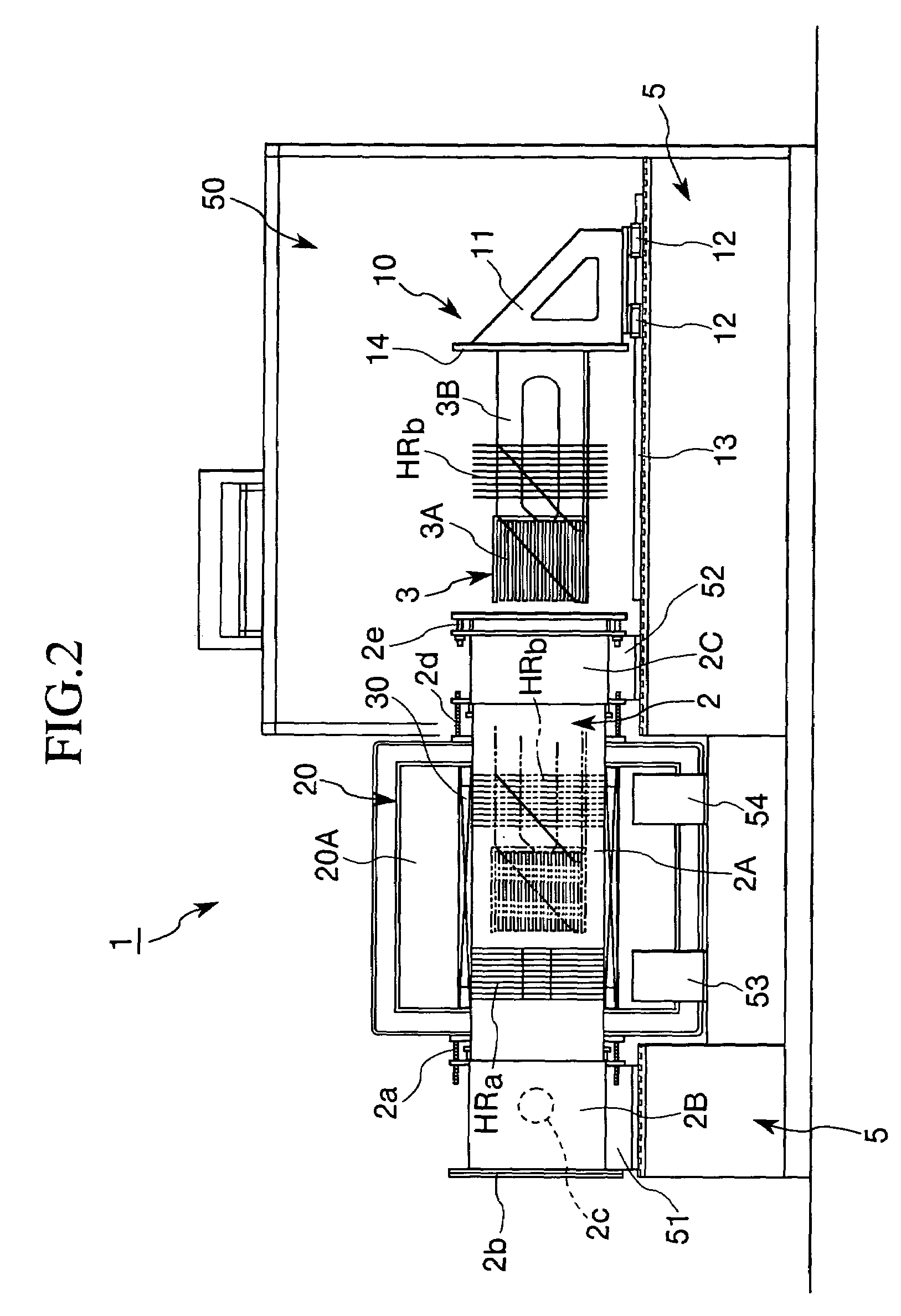
[0044]The heat treatment apparatus of the present invention will now be described further in detail with reference to the drawings.

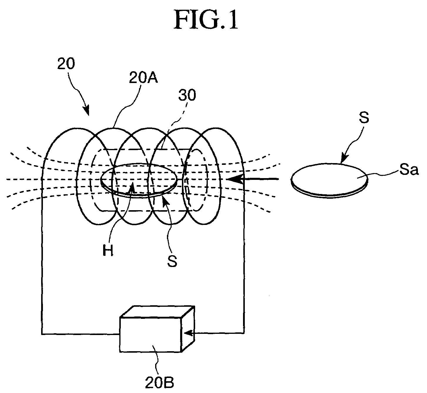
[0045]To begin with, the basic configuration of the heat treatment apparatus of the present invention will be described with reference to FIG. 1.

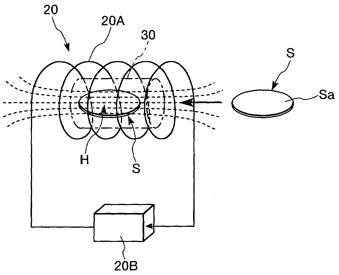
[0046]According to the present invention, a solenoid type magnet, i.e., an air-core coil 20A is used as a magnetic field generating device 20, and an object of treatment S which is a magnetic material is located at the center thereof. The air-core coil 20A is arranged so that the longitudinal center axis line direction thereof is substantially horizontal, and connected to the power source 20B. Relative to the object of treatment S located within the coil, the air-core coil 20A can impress a uniform magnetic field H in parallel with the main surface Sa of the object of treatment S. The object of treatment S is conveyed in the longitudinal axis line direction of the air-core coil 20A, and charged into the interior...


PUM

PropertyMeasurementUnit
surface temperatureaaaaaaaaaa
diameteraaaaaaaaaa
diameteraaaaaaaaaa

Abstract

In a heat treatment apparatus, the direction of the magnetic field generated by the magnetic field generating device in the region in which the object of treatment is heat-treated and the conveying direction of the conveying device in which the object of treatment is conveyed into the heat treatment vessel are in parallel with each other, and are in parallel with the horizontal direction of the entire heat treatment apparatus. The object of treatment is heat-treated with the main surface thereof arranged in parallel with the direction of the magnetic field generated by the magnetic field generating device in the heat treatment region.

Description

CROSS-REFERENCE TO RELATED APPLICATIONS[0001]This application is a continuation of International Application No. PCT / JP2004 / 001241, filed Feb. 6, 2004, which was published in the Japanese language on Aug. 19, 2004, under International Publication No. WO 2004 / 070747 A1, and the disclosure of which is incorporated herein by reference.BACKGROUND OF THE INVENTION[0002]The present invention relates to a heat treatment apparatus and a heat treatment method for carrying out a heat treatment in a magnetic field. More specifically, the invention relates to a heat treatment apparatus for applying a heat treatment in a high magnetic field to a finely patterned material or magnetic material, particularly a magnetic material such as an MR film, a GMR film or a TMR film.[0003]A magnetic film, such as a thin film of an Fe—Ni, Pt—Mn or Co—Fe alloy or the like, formed on a substrate by sputtering or the like, which is a magnetic material used for a magnetic head, an MRAM (Magnetic Random Access Memo...

Claims


Application Information

Patent Timeline
Patent Type & Authority Patents(United States)
IPC IPC(8): C21D9/62C21D1/04C21D9/00F27B5/04F27B5/12F27B5/13F27B5/14F27B14/08F27B14/14F27B14/16F27D3/12H01F41/22H01L43/08
CPCF27B14/08F27B14/14H01L21/00G11B5/3163G11B5/3903F27D3/12C21D1/04H01F41/22
Inventor UENO, HIROTO
Owner TOKYO ELECTRON LTD
Why Eureka
Try Eureka